Cathode: A Crt Compositor Node & Vse Modifier
 fridje


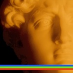
To install Cathode, add Cathode v1.0.blend from the included .zip file to your Blender asset library directory. If you do not have an asset library set up, create one by going to the Asset Libraries tab in your Blender preferences, and then add Cathode v1.0.blend to the library you select. Cathode will then be selectable in two places:
Method 1: Using Cathode as a modifier in the Blender Video Sequencer
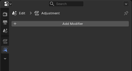
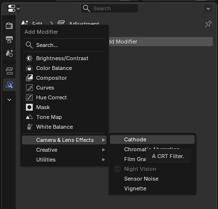
Cathode can be added to any video or image sequence track in the Video Sequencer, and also to adjustment layers. To easily create a new Video Sequencer workspace, create a new blend file either via file -> new, or Ctrl-N, and then from the new file submenu select "Video Editing". You can then drag your footage into the Sequencer timeline, or navigate to it using the file browser in the top-left workspace panel. From here, select the video track of your footage (make sure you select the video and not the audio track), and then select "add modifier" in the right-hand toolbar, like so:
Cathode can also be used as a node directly in the compositor. To do this, switch to the Compositing tab at the top of your Blender interface, either from a new file or an existing file. Click "New" to create a new compositor node tree, and then drag Cathode into your node tree from the bottom toolbar, like so:

Cathode can then be used within your compositor node tree like any other node.
An important note on video scaling and render resolutions
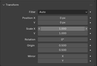
Cathode works best at higher resolutions, 4K especially, and at taller aspect ratios, 4:3 especially. It also works very well with low-resolution input images. If you wish to apply Cathode to some render or image that is already 4K, then no special scaling work is necessary, simply create a Video Sequencer or Compositor project at your desired final delivery resolution. However, if you wish to use Cathode with footage or images that are 1080p or lower, then some special attention is required to how your input images are scaled to fit your canvas. In the case of the Video Sequencer, when you add or drag in footage to the timeline, Blender will automatically scale it to fit your render resolution. We don't want this to happen with Cathode! Instead, you should head to this part of the toolbar and ensure that your clip's scale settings are set to 1.0 for both axis:
Below is a full explanation of every setting available in Cathode. Use this as a reference for what settings affect what features of your image, and enjoy! Feel free to get in touch if you have any questions :)
General Controls
- Background Color
Sets the background color present behind the filter. Works well with black or bright block colours like white or orange. Only active when the input image has an alpha channel and when "Preserve Alpha" (see below) is DISABLED. - Preserve Alpha
Disables the background color and preserves alpha of the input image through the filter process. Useful if you want to filter only part of an image to overlay it onto something else. - RGB Separation Multiplier
Offset multiplier for the RGB separation, in pixels. - Exposure
An additional exposure pass over the image that is applied before the rest of the effects. Can be used to boost or decrease the brightness of your image by entering a number measure in EVs. See the Exposure Node and Exposure Values (EVs) for more.
Scanlines
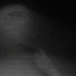
The Scanlines section simulates the brightness and darkness between a CRT's "scanlines", i.e. the lines created by the CRT's electron gun scanning across it's phosphor-coated screen. For realism here, the Line Count should be set to something similar to one of the many analogue video transmission standards that were created in the 20th century. The default setting is therefore the number of lines in one interlaced NTSC field, but this could be changed to, for example, the number of lines in a PAL field, or the number of lines produced by a high-resolution VGA display output. However, you must also take into account the pixel resolution of your actual rendered output, as a limited resolution will make these lines difficult to render. A good rule of thumb is to use the Y dimension of your render divided by 8, i.e. 2160 (Y dimension of a 4K image) divided by 8 is 270, which is also one interlaced NTSC field. In cases where that doesn't work, either increase the resolution of your render (scaling your input image to compensate, as described above), or reduce the number of lines set by the Line Count setting to whatever looks good. Adjust the other settings to taste, and use the Scanline Factor to dial in how much your overall image is darkened by this step.
- Scanline Factor
How strong the Scanline effect is, where 0 is off, and 1.0 is full strength. - Line Count
The number of CRT scanlines. 270 lines is 1/4 of 1080p and also the theoretical number of lines of one (interlaced) NTSC field. - Scanline Deadzone Thickness
How thick the darker part of each scanline is. - Scanline Thickness
How thick the brighter part of each scanline is. - Scanline Deadzone Brightness
How bright the darker part of each scanline is. - Scanline Brightness
How bright the brighter part of each scanline is.
Shadowmask
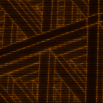
The Shadowmask section simulates the Shadowmask of a colour CRT, by procedurally generating a typical shadowmask grid pattern and overlaying it over the transformed input image. A CRT's shadowmask is analogous to (although not the same as) the pixel grid of an LCD, and as such is generally the limiting factor of it's resolution. Most CRTs had a finer pitch shadowmask than the resolution of the video formats they supported, and as such your Shadowmask Cell Count should be set to something higher than your Scanline Line Count. It is also good to use a Cell Count value that is not a neat multiple of your Scanline Line Count value. For this reason the default setting is 360, or 1/6th of a 2160p 4K image. If your shadowmask looks strange, or like it is just colored stripes, adjust the Corner Radius setting to a smaller or bigger value until it looks normal again. Use the Factor setting to adjust how much the Shadowmask section darkens your overall image.
- Shadowmask Factor
Amount of mixing between the original and shadowmasked images. - Shadowmask Cell Count
How many mask cells there are in both dimensions, i.e. a value of 256 will make a 256x256 grid of cells across the image. - Shadowmask Corner Radius
The radius of the corners of each color inside each showmask cell. Also affects how big the gaps are between the colors of each cell and between each cell.
Flicker
The Flicker section emulates the interaction between a camera's shutter speed and a CRT's scan cycle, by randomising the exposure of the input image between two exposure values, with a different random value per frame. Here, the greater the difference between the Minimum and Maximum Exposure settings, the more exaggerated the flicker effect will be. In general it is better to use a smaller difference between these values, both because a subtle effect is more convincing and for safety/accessibility reasons.
- Flicker Factor
Strength factor of the random flicker effect. - Flicker Minimum Exposure
Minimum exposure value, in EVs, that the flicker can come DOWN to. Can be less than 0, which would make the image darker than it is originally. - Flicker Maximum Exposure
Minimum exposure value, in EVs, that the flicker can go UP to. Can be less than 0, which would make the image darker than it is originally.
Distortion
The Distortion section simulates the physical shape of a CRT's glass envelope, the shape of which is necessary because of the internal vacuum all CRTs have. The default value should look believable for most situations, but in reality larger CRTs had less pronounced curvature and smaller ones had more pronounced curvature, so if you are aiming for a low-resolution, small, portable CRT look try increasing the distortion value, or likewise decreasing it for a larger CRT.
- Distortion Strength
The amount of distortion. 0 means no distortion, -1 means full Pincushion distortion, and 1 means full Barrel distortion. - Distortion Dispersion
The amount of chromatic aberration to add to the distortion. Can be a very useful effect for adding realism to the image, especially when simulating smaller CRTs, or monochrome CRTs. - Distortion Fit
Scales the image such that it fits entirely in the frame, leaving no empty/dark spaces at the corners. - Distortion Jitter
Introduces jitter while doing distortion, which can be faster but will also produce grainy or noisy results. This grain/noise is sometimes desireable when going for a certain look.
Dithering
One of the most useful and compelling features of Cathode, the Dithering section applies one of two types of Dithering to your input image, thus reducing it's color depth but also breaking up banding between visible color steps in gradient areas. This effect is very useful for simulating how older computers and game consoles would render an image, and for stylising your render in general. The two available dithering types are:
- 8x8 Ordered Bayer dithering, which uses a generated threshold map to create the iconic pattern-based dithering used by many early computer programs and video games.
- Random Noise dithering, which uses a unique white noise texture as a threshold map to break up color step edges with random noise.
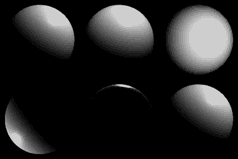
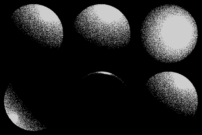
Right: White Noise Dithering with 1 colour step.
Use Ordered Bayer when you want a video game or computer-style look, and use Random Noise when you want to embrace a noisy, lo-fi, analogue look.
- Monochrome
Enables monochromatic dithering mode, which mixes between only the two mono colors selected below. - Color Steps
The number of color steps per channel. The total number of possible colors present in the image is this value cubed. - Color Bias
A per-channel multiplier to boost the brightness of each channel if needed. Leave this set to 0 unless you need to boost the brightness of a given color channel. Set to a number between 0 and 1 to reduce the brightness of a given color channel. - Mono Dither Color Highlight Color
Dithering colour for brighter pixels. Only active when Monochrome is enabled. - Mono Dither Shadow Color
Dithering color for darker pixels. Only active when Monochrome is enabled. - Randomise Seed per Frame
Change the seed every frame to generate a moving noise pattern. Only relevant for Noise dithering, unused by Ordered dithering. - Noise Seed
Seed for the noise pattern used for dithering. Disabled when randomised seed is active. Only relevant for Noise dithering, unused by Ordered dithering.
Composite Signal Degradation
The Composite Signal Degradation section emulates two features of a Composite video signal:
- How the mixing of chroma and luma signals makes an image's features blur together along the length of a scanline
- How the mixing of chroma and luma signals over an unshielded cable adds signal noise to both signals.
The first effect here is labelled Composite Blur. The second is labelled Composite noise. Increase the settings in this section to further degrade your image, and decrease them to clean it up.
- Composite Blur Factor
Factor of the Composite Blur effect, 0 is off, 1.0 is fully on. - Composite Blur Type
Type of blur kernel used to add horizontal blur to each scanline. - Composite Blur Size
The size of the horizontal blur added to each scanline, in pixels. - Composite Noise Factor
Factor of the Composite Noise effect, 0 is off, 1.0 is fully on. - Composite Luma Noise Strength
How strong the added noise is in the image's Luma signal. - Composite Chroma Noise Strength
How strong the added noise is in the image's Chroma signal.
Dot Crawl
The Dot Crawl section aims to emulate Composite Dot Crawl. It does this by using a kernel filter to detect shadowed areas in the image, and then mixing a per-frame-inverting checkerboard pattern into those areas. As such it is usually best to leave the bottom two settings alone and instead play with the Strength value and the Factor to achieve your desired effect.

- Dot Crawl Factor
Factor of the Dot Crawl effect, 0 is off, 1.0 is fully on. - Dot Crawl Strength
Strength of the Dot Crawl effect. - Dot Crawl Scale
Size scale of the Dot Crawl effect relative to the image resolution. 1.0 = dots the same size as the image pixels. - Dot Crawl Detection Filter Type
Type of detection filter used by the dot crawl effect. Shadow is generally the most realistic here, but feel free to experiment :)
Composite Echo
The Composite Echo section emulates how hard edges in composite video signals can be "echoed" along the width of an image by high frequency signal effects like capacitance and reflection. To do this it finds the positive horizontal derivative of the input image, copies areas of that derivative that are higher than a given threshold lengthways in the image multiple times, and then mixes that back down into the input image. The Threshold value therefore controls how much change over a small area is needed in order for that image feature to be echoed, and the Echo Distance controls how much distance there is between echos, in pixels. In the current version of Cathode, there are three echoes. This cannot currently be controlled by the user due to limitations with compositor nodes.
- Echo Factor
Factor of the Composite Echo effect, 0 is off, 1.0 is fully on. - Echo Threshold
How bright a pixel needs to be to be echoed, pixels brighter than this threshold get echoed. - Echo Distance
Distance between each image echo, in pixels.
Glare
The Glare section simulates how the light coming from our imaginary CRT would interact with a camera's lens and sensor. The controls in this section mirror the standard Blender Glare node.
- Glare Factor
Factor of the glare, 0 is off, 1.0 is fully on. - Glare Type
Type of glare filter used. Bloom and Fog Glow are the most realistic for a CRT, but some really crazy and cool effects can be achieved by playing with this setting :D - Glare Quality
Quality of the glare filter. Low is fastest to render, but the lowest quality/most accurate, High is the slowest to render, but the highest quality/most accurate. - Glare Threshold
The brightness level at which pixels are considered part of the highlights that produce a glare. - Glare Smoothness
The smoothness of the extracted highlights. - Glare Clamp
Clamp bright highlights. - Glare Clamp Maximum
Clamp bright highlights such that their brightness are not larger than this value. - Glare Strength
Adjusts the brightness of the glare. - Glare Saturation
Adjusts the saturation of the glare. - Glare Tint
Tints the glare by this color. Consider desaturating the glare to get more accurate tinting. - Glare Size
The size of the glare relative to the image. 1 means the glare covers the entire image, 0.5 means the glare covers half the image, and so on.
Transform
This section is used to control the shape and position of your image before it is processed by any of Cathode's sections. It mirrors the standard Blender Transform node.
- X
X Offset in Pixels - Y
Y Offset in Pixels - Angle
Angle to rotate the entire node group by - Scale
Scale of the entire node group. Use this to make low resolution images fit a high resolution render. - Interpolation
Transformation interpolation method, "nearest" is both the fastest and best to use for low-resolution images that you are scaling up and filtering with Cathode. - Extension X
The extension mode applied to the X axis, i.e. how the edges of the image are handled when they are visible. - Extension Y
The extension mode applied to the Y axis, i.e. how the edges of the image are handled when they are visible.
-
$35
Price for a single user, i.e. any individual customer.
-
$150
Price for a whole business, for R&D Purposes. You will receive priority support if needed.
-
$350
Price for a whole business, for R&D, production, or commercial use. You will receive priority support if needed.
 Included
Includes 12 months of
- Support from fridje
- Product updates
Extend this product’s Support Period +12 months: 50% of product price
Have questions before purchasing?
Login to message
| Dev Fund Contributor | |
| Published | about 2 months ago |
| Blender Version | 5.2 |
| Render Engine Used | Cycles, Eevee, Freestyle, Luxrender |
| License | GPL |