cvELD Quick UV Checker
 Color Variations of Eldorado - cvELD -
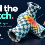
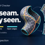
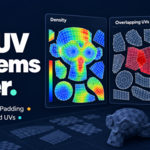
See display issues at a glance
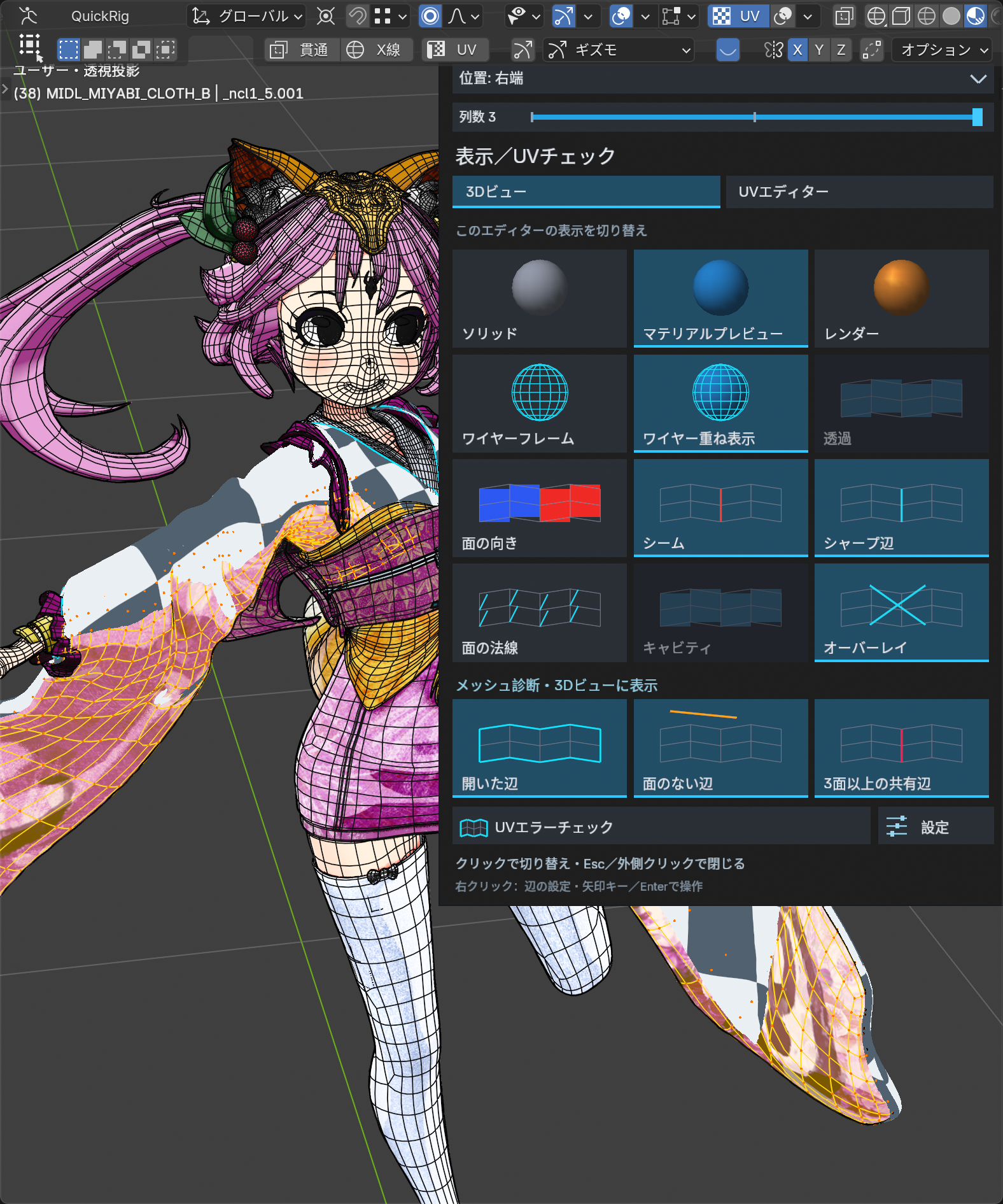
Actual Blender capture, Japanese interface. English controls are also included.
The Display / UV Check menu groups visual switches into illustrated cards. Press the overlay icon immediately to the right of the UV header button in the 3D View or UV Editor.
- Choose 3D View or UV Editor.
- Click a card to toggle its display. Blue cards show active settings; unavailable cards are dimmed.
- Use UV Error Check for UV diagnostic results, or Settings for edge colors, line width, targets and visibility through surfaces.
In the 3D View, compare shading, wire overlays, face orientation, seams and normals. In the UV Editor, compare angle/area stretch, UV edges/faces, island borders, seams and sharp edges. Mesh diagnostics distinguish open edges (cyan), loose edges (orange), and edges shared by more than two faces (pink). Loose edges have no UV location.
The diagnostic edges follow the final viewport-evaluated modifier result and update on animation frame changes. In Edit Mode, the modifier's display switches determine the visible result. A Solidify modifier that closes an opening therefore removes that opening from the diagnostic. The original mesh and UVs are not changed.
Choose a left/right/top/bottom position and 1–3 columns. Close with Esc or an outside click; right-click opens edge settings. Arrow keys and Enter operate the cards.
This menu is included in Quick UV Checker. No other add-on is required. Native display settings retain Blender's mode/shading restrictions. Dense evaluated meshes can slow playback; narrow the targets or reduce subdivision while inspecting.
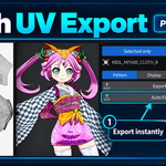
Batch UV export — PNG, SVG and PSD
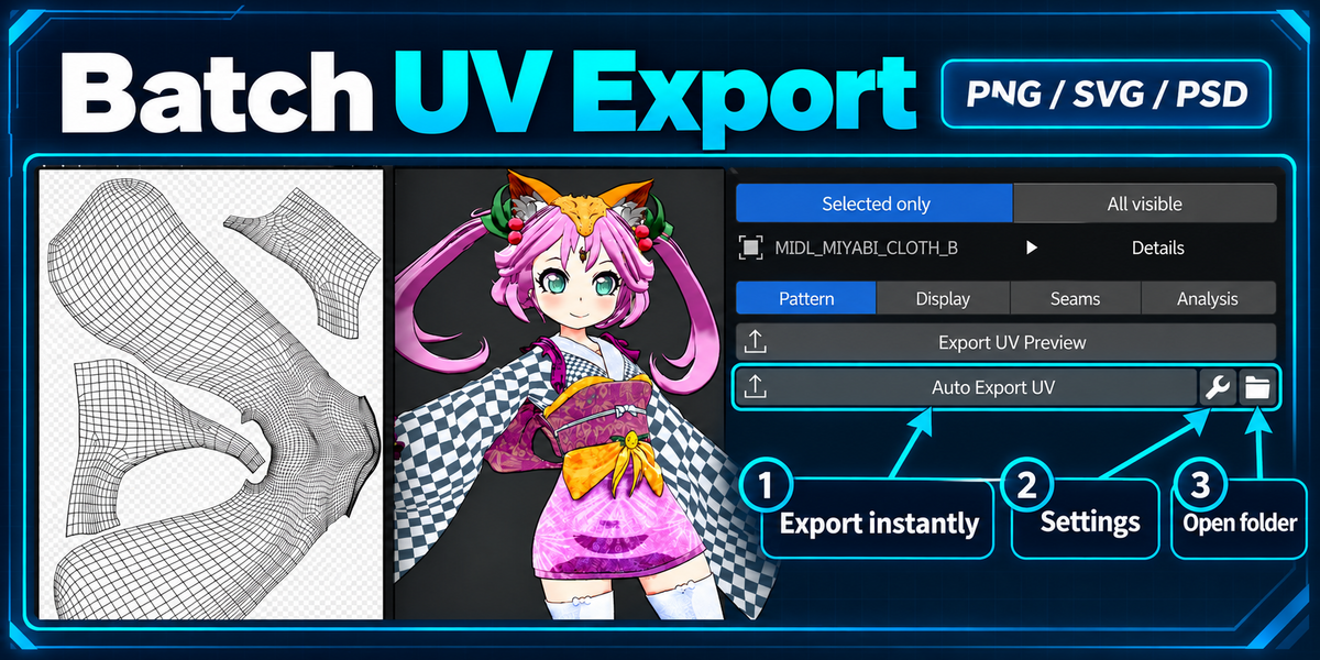
New in 1.4.0: export the preview as a transparent PNG, vector SVG or layered PSD. Open the Pattern tab.
- Select the UV-bearing objects to export. With Selected only, an empty selection shows a warning.
- Press Auto Export UV to export immediately using saved settings. The default is UV edges only, on a transparent 2048 × 2048 PNG.
- Press the small folder icon to open the output folder. By default, a single UV folder is created beside the saved .blend file.
Use the wrench at the right of Auto Export UV to change and save its settings. Saving settings does not export files. A custom output folder overrides the scene-based location. For an unsaved scene, save the .blend first or set an output folder.
Choose a format and content
| Format | Use |
|---|---|
| PNG (transparent) | UV edges or the checker pattern as an RGBA image. |
| SVG | UV edges, the checker, or both as vector artwork. |
| PSD (layers) | Checker and UV Edges on separate layers, with lossless ZIP compression and transparency. Choosing both with PNG automatically selects PSD. |
Opacity, checker pattern and colors follow the preview. Adjust UV line color, width, image size, UV range and outside-island transparency in export settings. Layers can be edited separately in a PSD-capable painting tool; individual application compatibility can vary.
Batch targets and filenames
Automatic export groups material faces by saved texture references, removes duplicate UV layouts, and puts all files in the same folder. Multiple color or normal maps using the same UV layout therefore produce one layout. Enable All Patterns to export all 14 patterns. Use Export UV Preview for a manual export of the current combined target or a separate file per object; it also supports all-pattern batches.
Filenames get an automatic prefix. Change its rule in Preferences using {object}, {material}, {texture} and {uv}. The default is {object}_{material}_{texture}. Export settings and the naming rule are included in portable preference JSON. Existing files are overwritten only when that option is enabled.
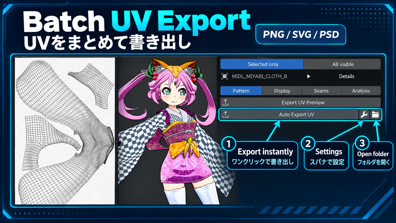
Annotated illustration based on a Blender capture: export immediately, configure with the wrench, and open the destination with the folder icon.
Start here
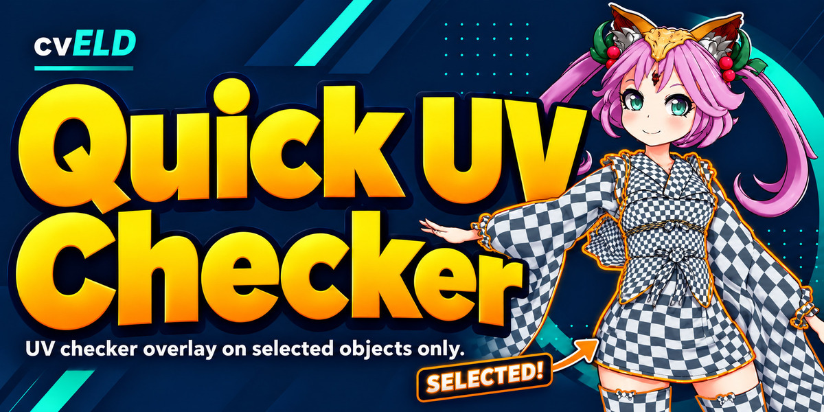
Inspect UV patterns, stretch, seams and UV health while keeping your materials and UV coordinates intact. Open Sidebar → Quick UV Checker in the 3D View or UV Editor. The 3D View header also has a UV button beside X-Ray; its dropdown opens the same settings.
- In any mode, use a visible object with UV-bearing surfaces. You can keep Sculpt, Vertex Paint, Weight Paint or Texture Paint active.
- Press Show UV Checker, or the header's UV button.
- Choose a pattern and inspect the surface. Press Hide UV Checker to return to your usual view.
The checker is a temporary viewport display. It does not create checker materials or images, edit UVs, unwrap, repair or appear in the final render.
Install and update
Blender 4.5 or later is required. Windows with Blender 4.5.0 LTS and 5.2.2 LTS has been tested; macOS, Linux and other graphics backends have not been validated. QuickBaker is not required.
- Keep your supplied extension ZIP intact. Drag it into Blender and confirm installation, or use Preferences → Add-ons → Install from Disk.
- Enable cvELD_QuickUVChecker.
- Open the Quick UV Checker sidebar and follow the first workflow above.
For an update, end the checker display first and install the replacement ZIP through Blender. Restart Blender if an earlier copy remains loaded. Disable the former cvELD UV Inspector or an old QuickBaker embedded prototype before enabling this standalone product. To uninstall, hide the checker, then disable or remove the extension in Preferences.
Choose targets and a tab
Target selection stays above the tabs. Selected only is the default; All visible includes visible surfaces in the current view layer, including objects outside the active edit session. Hidden objects are excluded. These displayed objects share one atlas during analysis.
Open Details beside the target to enter a UV map or named UV attribute. Leave the name blank for automatic lookup. A named inspection UV does not change active, render or bake UV flags; objects missing that UV are omitted and reported.
| Tab | Use it for |
|---|---|
| Pattern | Pattern cards, frequency, display aspect and checker color. |
| Display | Opacity, UV Editor display, directional stretch and UV guides. |
| Seams | Marked seams, actual UV cuts and open mesh edges. |
| Analysis | Run UV health checks, choose categories and inspect results. |
Switching tabs preserves settings and running analysis. Small triangles expand details; target details and result details start folded. Pattern cards remain visible in the Pattern tab. X beside a number resets that value to its default. Reset Checker Settings resets the checker display and enabled analysis checks. Numeric analysis settings such as texture size, target density and padding are retained. Color adjustment has its own reset. After a reset, press Undo Reset beside the reset button to restore the previous settings in any mode. Object Mode also supports Blender Undo/Redo; use Undo Reset in Edit Mode.
Choose patterns and display aspect
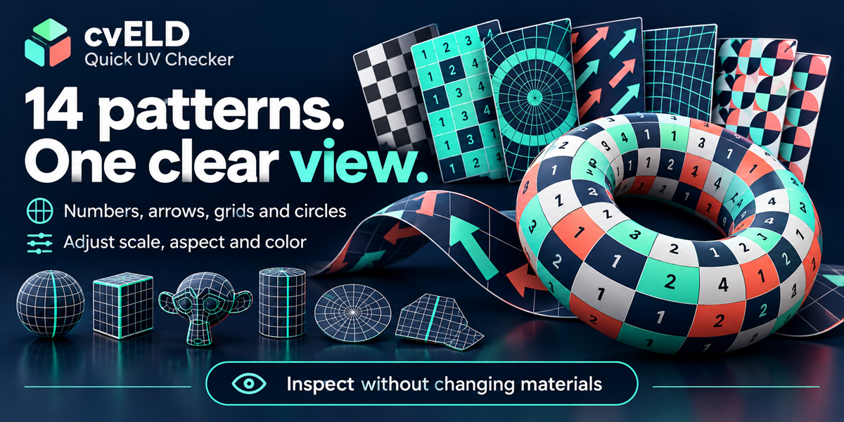
- Open the Pattern tab to view the available pattern cards.
- Click a card's name. You can press and drag across names to switch immediately.
There are 14 original patterns. Squares and circles reveal stretching; grids and diagonals show bending and shear; arrows, gradients and numbered patterns help read position and orientation.
| Setting | Visible effect | Default |
|---|---|---|
| Tiles per UV Unit | Higher values give finer cells; lower values make distortion easier to see at a distance. | 16 (range 1–512) |
| UV Aspect (W/H) | 1 is square. Above 1 makes cells wider; below 1 makes them taller, in both editors. It changes display only. | 1 (range 0.125–8) |
Use ×2, ×5, ÷2, ÷5 below the frequency field. Fractions round to the nearest integer, within 1–512. The aspect buttons set width:height to 0.5:1, 1:1, 2:1 or 4:1. Numeric entry and individual X resets remain available.
Read rotation and mirroring
Direction Grid points along +V; the detached tail dot is on the +U side. A U mirror swaps the dot side; a V mirror reverses the arrow. Coordinate Beacon puts U above V with asymmetric corner marks. Its cell numbers restart in each UV tile and repeat after 100 cells. Direction Grid repeats across UV units, including negative UVs and UDIMs.
Make the checker easy to read
In Pattern, expand Color adjustment. Start with Exposure (EV), Contrast and Saturation; Tint changes the overall color. For supported patterns, enable Custom two-color palette and choose A/B. The swap button exchanges them. Patterns without this option keep their source palette.
Advanced color includes hue, gamma, contrast pivot, RGB gain/offset, invert, strength and output clamping. Gamma above 1 brightens the checker. Strength blends the adjustment with the original pattern. All changes affect the checker in both editors; scene color management, materials and image pixels remain unchanged.
Diagnostic and distortion colors stay unchanged so warnings remain readable. You can still edit color settings during diagnosis. Press Return to pattern display to inspect the adjusted pattern; analysis keeps running and its results remain available.
Uncheck Color adjustment to bypass it while retaining your settings. Use the X beside a number for a single default, or Reset Color Adjustment for the entire grade and palette.
Sync the 3D View and UV Editor
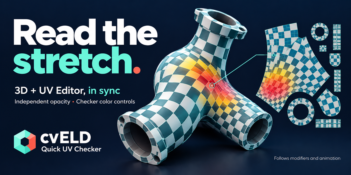
Open Display. Opacity (3D / UV) adjusts the checker in both editors together. Enable Show in UV Editor to display it there. Dim UV to 1/3, available in Display and expanded Seams, reduces checker brightness without changing textures. Pattern, frequency, aspect and color stay synchronized.
Limit pattern to image confines the pattern to the displayed image bounds. Choose Image 0–1 for the first tile or Image UDIM tiles for the displayed image’s registered tiles. The reference size does not change UVs or the image. The checker and diagnostic overlays can display in Object Mode too. Use mesh Edit Mode to edit UVs and see Blender’s native UV outlines. Geometry Nodes evaluated output may differ from the editable UV cage.
In the 3D View, Solid, Wireframe, Material Preview and Rendered shading work with the checker. X-Ray and disabling ordinary overlays do not hide it. Occlusion follows filled visible surfaces; the checker does not show a target's back surface through its front. Unselected wireframe objects do not provide filled-surface occlusion. Disable an active Alt+B clipping region. The checker can be toggled in any mode without leaving the current tool. UV-bearing evaluated surfaces are required; it does not create UVs for geometry that has none.
Find directional stretch
Enable UV Distortion and expand its details. Yellow to red shows increasing directional stretch; magenta marks collapsed UVs. Red at Stretch Ratio controls the display range. Uniform UV scale is not directional distortion; use density analysis to compare overall resolution.
Distinguish three kinds of edges
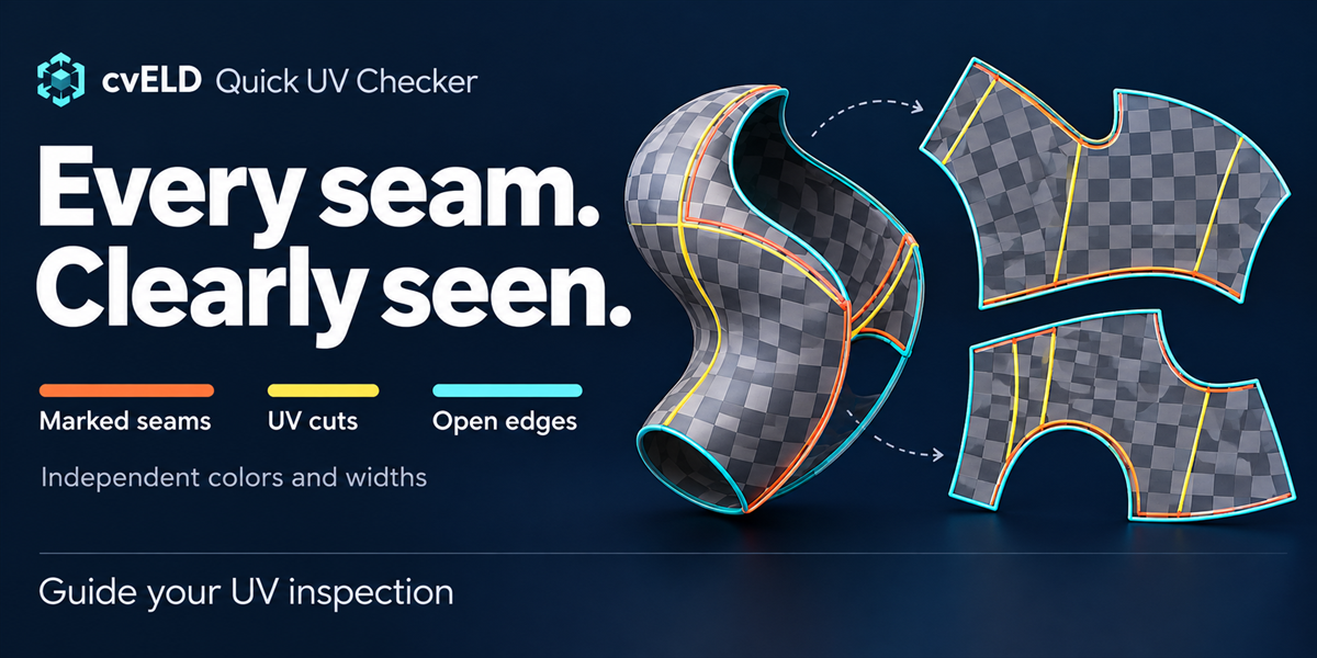
Open Seams, enable Highlight Seams and expand its details. Each category has an independent checkbox, color and width in both editors.
| Category | What it shows | Default color |
|---|---|---|
| Marked UV seams | Edges marked as seams in Blender. Their UVs may still be continuous. | Orange |
| UV discontinuities | Actual UV splits between faces sharing a mesh edge, even if the edge is unmarked. | Yellow |
| Open mesh edges | Physical boundaries with only one adjacent polygon. | Cyan |
Widths start at 1 screen pixel and range from 1–8 px, independent of interface scale. Use X to reset an individual width. Where categories coincide, cyan draws last. The green UV island borders in Display are a separate layer.
Run UV health checks
- Choose the target objects, then open Analysis.
- Expand Analysis settings and enter texture width/height, target density and minimum padding if needed.
- Press Analyze UV Health.
- Expand Diagnostic results and click a result row to highlight affected triangles in the 3D View and UV Editor.
Realtime analysis is on by default. After UVs, geometry, targets, scene units or analysis settings stop changing for about 0.3 seconds, results update automatically. You can keep editing while calculation runs; this is not a per-frame guarantee. Turn realtime off to update manually with Analyze. Stop ends analysis mode; independent UV display aids can still request their own calculations.
Expand Enabled checks to choose seven categories. Disabled categories have no active result view or issue count. All displayed objects are compared as one shared atlas, so unrelated objects may overlap intentionally. Start with Selected only to narrow the scope.
Counts are unique evaluated faces, including instance copies. All issues combines warnings, without a synthetic score; exact stacks are informational and excluded. Highlights mark involved triangles. They do not select, unwrap or repair geometry.
Changed result rows and counts are unavailable until recalculation. During realtime updating, the last compatible diagnostic overlay may remain visible until the new result is ready. An Incomplete message means zero counts are not an all-clear: reduce the targets and analyze again. The triangle limit is one million, and very complex topology or pair searches also have bounded limits. Missing or invalid UV surfaces are reported separately.
Read each diagnostic
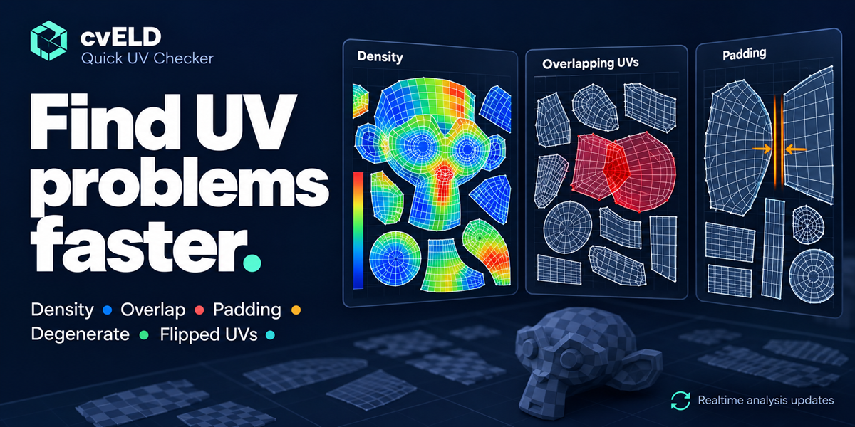
Texel Density
Set texture dimensions and Target px/m. Density reflects texture pixels per metre of world surface, including object transforms and rectangular textures. Scene unit scale applies; None means one Blender unit is one metre. Defaults are 2048 × 2048, 1024 px/m and ±10% tolerance. Blue is below target, green is target, red is above. The tolerance controls counts; the heatmap varies continuously.
Partial overlap, self overlap and exact stacks
Red means positive-area overlap between UV regions; touching edges alone do not count. Purple self overlap is within the same UV island, including folded quads and n-gons. Blue exact stacks are two non-self-overlapping islands covering the same area, including different triangulations. Intentional stacks are informational. Tiny intersections below numerical tolerance are ignored.
Padding
The default minimum is 8 px between different island boundaries, using the configured texture width/height. Orange marks insufficient clearance and adjacent triangles. Overlap and exact stacks are classified separately. Enable tile-border checks: 0–1 checks one atlas; UDIM checks local tile edges and warns about cross-tile edges. Each UDIM tile uses the same resolution. Gaps within one island and image alpha are not checked.
Degenerate and flipped
Magenta flags UV triangles at or below the area threshold (default 0.01 px²), or zero-area world triangles. Collapsed UV positions have cross markers. Purple flipped UVs have reversed UV winding relative to triangle ordering, excluding degenerate triangles. Mirrored UVs can be intentional; mirroring an object transform alone is not this winding test.
Inspect UV coverage and borders
In the UV Editor → Quick UV Checker → Display tab, press UV overlap debug. It shows only the intersecting UV area in red and island borders in green. Expand its details to switch those layers independently, change opacity, border color and width. Results update after edits pause. If overlap regions are limited, reduce the target set.
Expand UV display aids to choose the following display-only guides.
| Guide | What to look for |
|---|---|
| UV coverage | The image area covered by target UV surfaces. |
| Odd coverage | Areas covered an odd number of times. Identical paired stacks cancel, so this is not an overlap all-clear. |
| Matching cut edges | Matching colored tabs identify the same mesh edge on split UV islands. |
| UV corner X marks | White X marks show corner positions. |
| Dim UV image | Darkens only the displayed image to help read overlays. |
| Reference grid | Use UV-unit or image-pixel spacing. It does not enable snapping. |
Red overlap and odd coverage are mutually exclusive. Odd coverage supports up to 12 visible tiles at a time with a 512-pixel mask per tile; zoom in for a wider atlas. Guides do not change UVs, selection, materials or image pixels.
Inspect generated surfaces
Geometry Nodes meshes and unrealized instances, collection instances, beveled curves, NURBS surfaces and text can be inspected when their evaluated faces carry UVs. No conversion, modifier application or realization is required. Mesh output generated from curves, hair curves and point clouds is also supported when it carries UVs.
- In Geometry Nodes, connect a primitive's UV Map output to Store Named Attribute.
- Use a Vector attribute on the Face Corner domain and a name such as uv_map.
- Select the generator and show the checker. If necessary, enter that name in target Details.
Named 2D/vector attributes on face corners or points use their first two components. Automatic lookup searches UV-prefixed names. Anonymous fields, shader Generated coordinates and shapes without UV-bearing faces do not provide an inspection UV. Create or store UVs with Blender first. In mesh Edit Mode the edit cage is normally used; nodes with edit-mode display enabled may show evaluated output instead. Hidden edit-cage faces are excluded.
Inspect modifiers and animation
- Select the UV-bearing mesh and show the checker.
- Adjust a modifier, scrub the timeline or play the animation. The overlay follows the evaluated surface at the current frame.
- In Edit Mode, enable the modifier’s Show in Edit Mode option to inspect its evaluated result. With it disabled, inspect the editable cage.
In Pose or Armature Edit Mode, Selected only includes visible meshes deformed by the active armature. Select the rig and pose it to check the pattern on its meshes. UVs and original materials remain unchanged.
Large evaluated meshes need new display data each frame and can slow playback. Reduce visible targets or subdivision levels while checking movement. The demonstration is assembled from consecutive Blender frame captures; it is not a playback-speed measurement.
Keep the controls you use
Open Preferences → Add-ons → cvELD_QuickUVChecker. Under Visible controls and Visible patterns, uncheck items you rarely use. These preferences hide controls or cards; they do not reset their values or switch off active overlays. Turn the actual overlay off before hiding its controls.
The Pattern tab always shows the cards enabled in Preferences. Hiding a card does not change the current pattern. Export Preferences JSON saves visibility choices for another installation; Import Preferences JSON validates and restores them, keeping a backup of the current preferences. Visibility recovery is stored outside the replaceable add-on folder. These visibility preferences are separate from the temporary checker values.
Troubleshooting and ending a session
| Symptom | Action |
|---|---|
| Nothing appears | Use a visible UV-bearing surface in the current mode, show the checker, clear an incorrect UV name and disable Alt+B clipping. |
| A control is missing | Choose the correct tab, expand its triangle, then check Visible controls in Preferences. |
| Color changes are not visible | Enable Color adjustment and press Return to pattern display. Diagnostics and distortion deliberately retain their own colors. |
| UV Editor is empty | Enable Show in UV Editor and increase its opacity. Use mesh Edit Mode for native UV outlines. Check image/tile bounds. |
| Results disappeared | Wait for realtime updating or analyze again after the target/UV/settings change. |
| Analysis is slow or incomplete | Use Selected only, reduce objects and disable checks you do not need. |
| Pattern looks flat at a distance | Zoom in or reduce Tiles per UV Unit. |
| Drawing error | Record Blender version, graphics backend, visible warning and console message; contact support through your purchase page. |
Hide UV Checker ends the display; Stop ends analysis. Independent guides have their own switches. Display sessions end on scene/view-layer change, loading a file or disabling the add-on. Display toggles do not add an Undo step; ordinary UV editing still uses Blender Undo. Mesh size and hardware affect responsiveness.
Current controls and license
The current interface groups settings into Pattern, Display, Seams and Analysis. It includes draggable pattern cards, numeric default resets, display aspect, checker color adjustment, selectable display targets, automatic analysis updates and independent seam categories. Visibility preferences can be recovered with JSON.
Version follows the installed extension (current manifest: 1.4.0). Licensed under GPL-3.0-or-later, without warranty; see the supplied LICENSE file.
Add your own square patterns
- Open Pattern and press + beside Custom Patterns.
- Choose a square still image. Width must equal height; there is no resolution whitelist or fixed entry limit.
- The new image becomes active. Click a name to switch; use its X to remove the registration without deleting the source file.
Frequency, aspect, color and opacity also apply to custom patterns. The 3D View, UV Editor and PNG/PSD preview export share the selected image. Custom image patterns cannot be exported as vector SVG; UV-edges-only SVG remains available. Registrations are saved with Preferences recovery and JSON import/export. Images remain external references: keep them at the registered paths. If an image is unavailable, remove its registration and add it again.
Version history
1.5.0 — 2026-11-03
- Added square custom pattern images with a + button, arbitrary resolutions and no fixed registration limit.
- Added the built-in Display / UV Check menu immediately beside the UV header button.
- Added the illustrated display-menu guide and examples for both editors.
1.4.0
Transparent PNG, vector SVG and layered PSD UV export; automatic export, saved settings, output-folder shortcut and customizable naming.
Have questions about this product?
Login to message
| Blender Extension Compatible | Yes |
| Published | 6 days ago |
| Blender Version | 4.5 - 5.2 |
| Extension Type | Add-on |
| License | GPL |