 KV Studio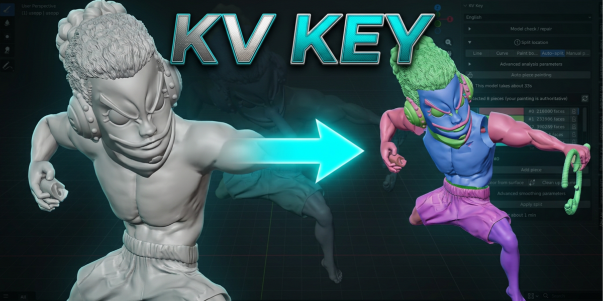


Installation
1. Blender version : 4.3 or newer.
2. Open Edit → Preferences → Get Extensions.
3. Click ▼ (top-right) → Install from Disk… and pick `kv_key-1.0.0.zip`.
4. Enable it, then press N in the 3D Viewport and switch to the KV Key tab.
5. The language dropdown at the top of the panel switches between English and 繁體中文; panel text updates immediately (a few tooltips only refresh after re-enabling the add-on).
Panel overview
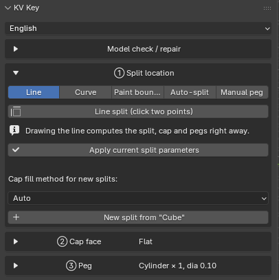
Model check / repair ← preprocessing, collapsed by default
├─ Separate into individual objects
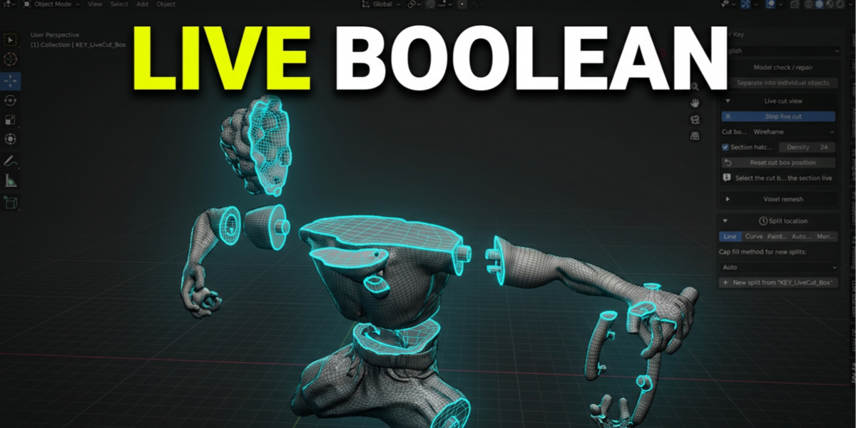
├─ Live cut view
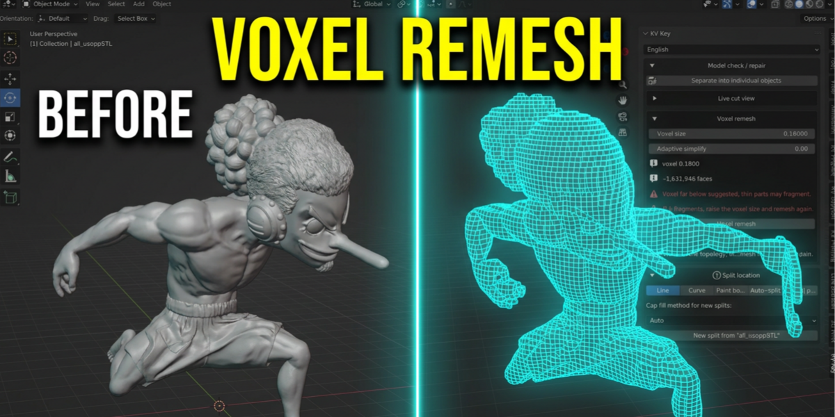
└─ Voxel remesh
Split list ← every joint you have created; a check mark = cap/pegs done
① Split location ← Line / Curve / Paint boundary / Auto-split / Manual placement
② Cap face ← shape, fill method, cap editing
③ Peg ← peg editing, generate pegs
Quick start
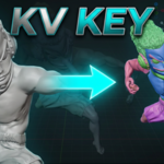
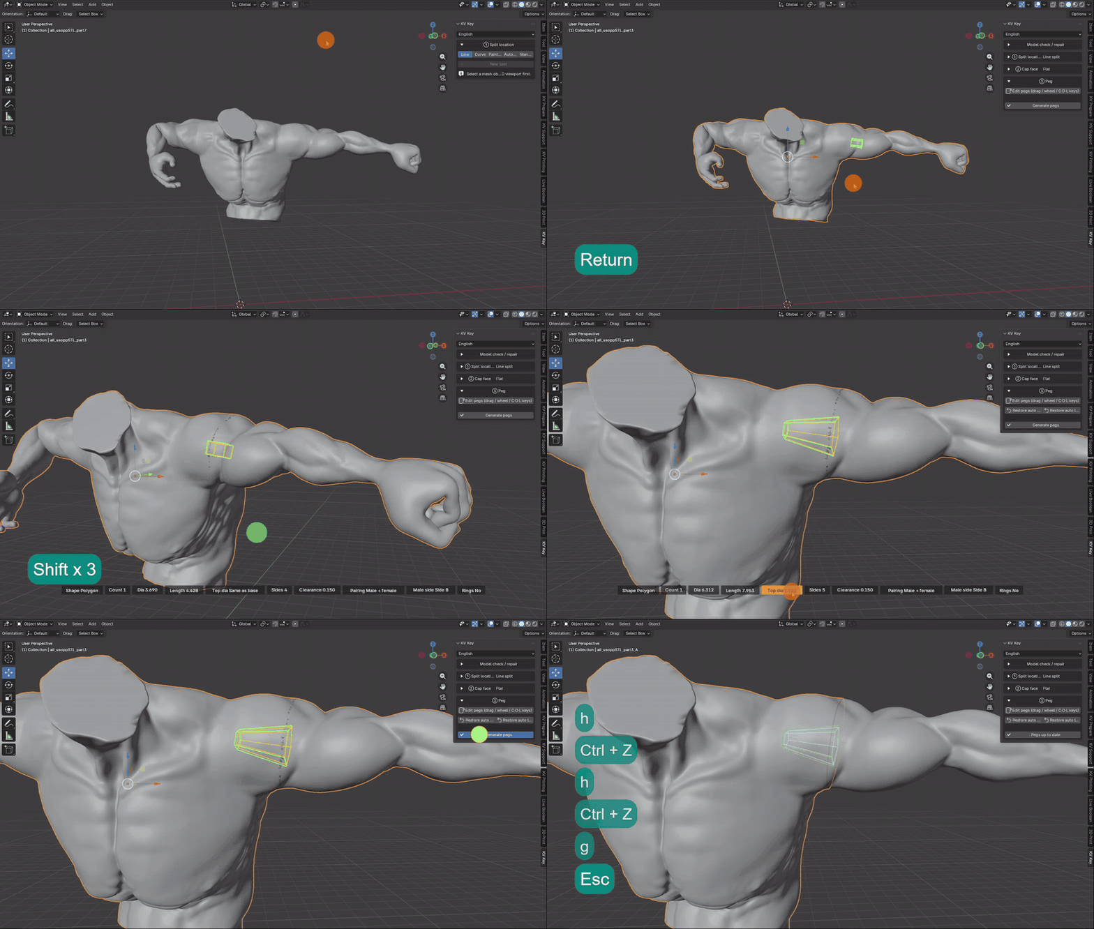
The shortest path: select the model → pick Line in ① → press Line split (click two points) → click two points across the model → Enter.
Five ways to place the split
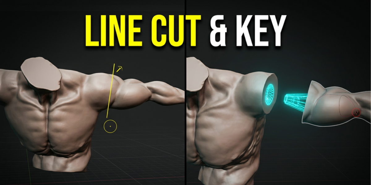
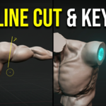
Line : Arms, necks, bases — anywhere a single flat cut works
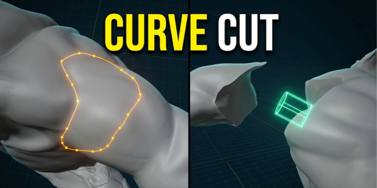
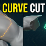
Curve : Following a natural line of the sculpt and cutting out a region
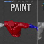
Paint boundary : Seams that must hug sculpted detail, placed with a brush
Auto-split : Breaking a whole figurine into many pieces, analysis first
Manual placement : Parts that are already separate — you only want pegs
Curve split
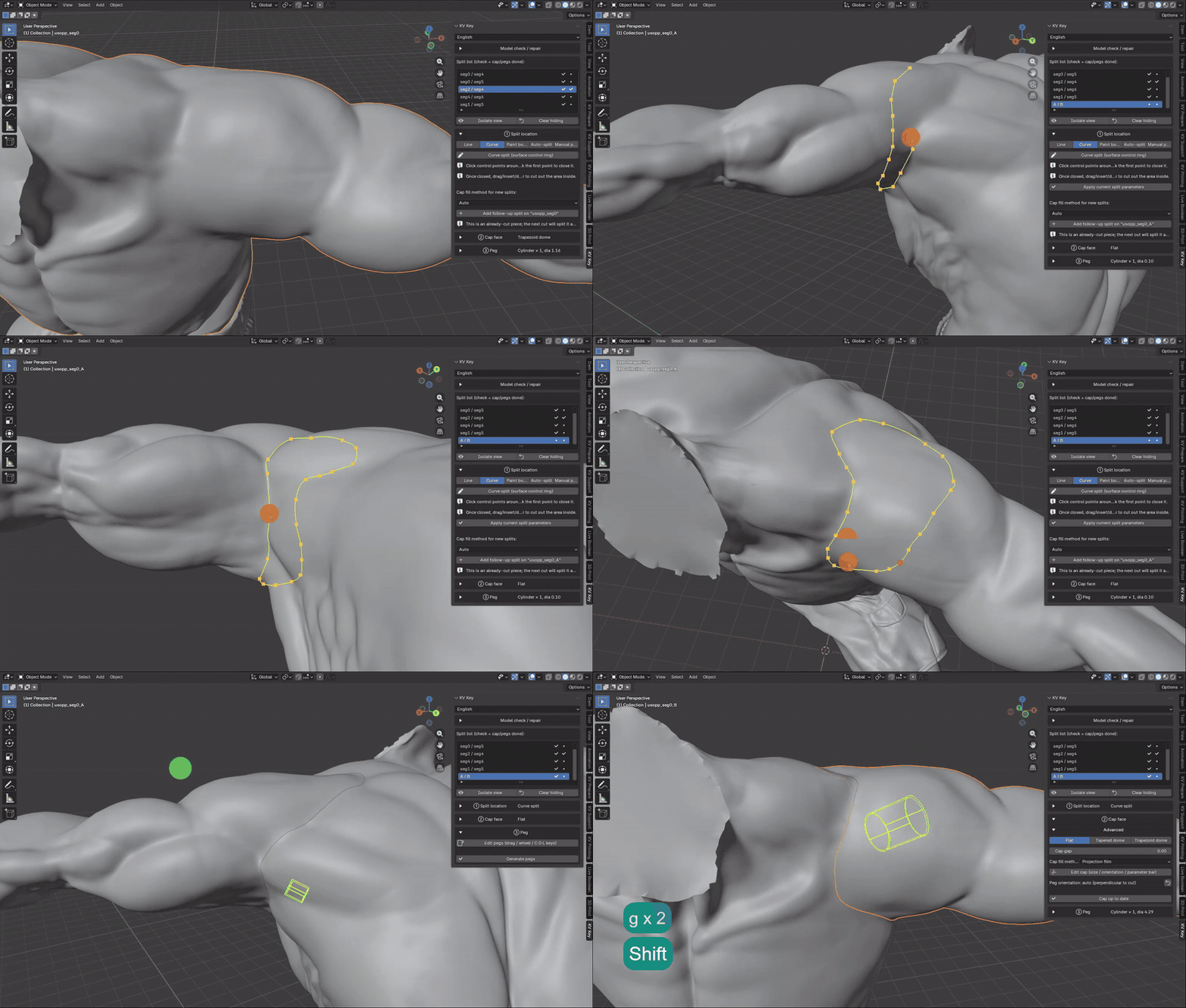
- Left-click to place control points; "click back on the first point" to close the ring.
- After closing you can keep editing: drag existing points, click on a segment to insert a point, X to delete one.
- Enter confirms and cuts, Esc / right-click cancels (cancelling changes nothing).
Paint boundary split
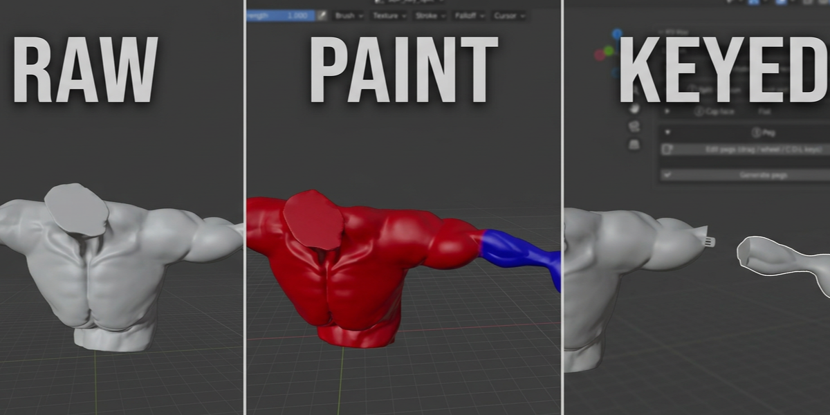
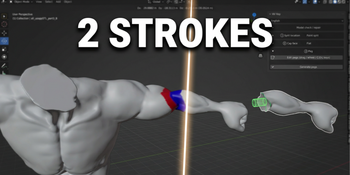
Paint the boundary with vertex colors and the tool cuts along it. "Paint split (enter painting)" switches the model into Vertex Paint; when you are done, return to the panel and press "Apply paint split".
Three modes, three ways to paint:
① Fill both colors — fill each of the two regions completely with color A and B; the cut runs along the boundary (anything left unpainted counts as side B).
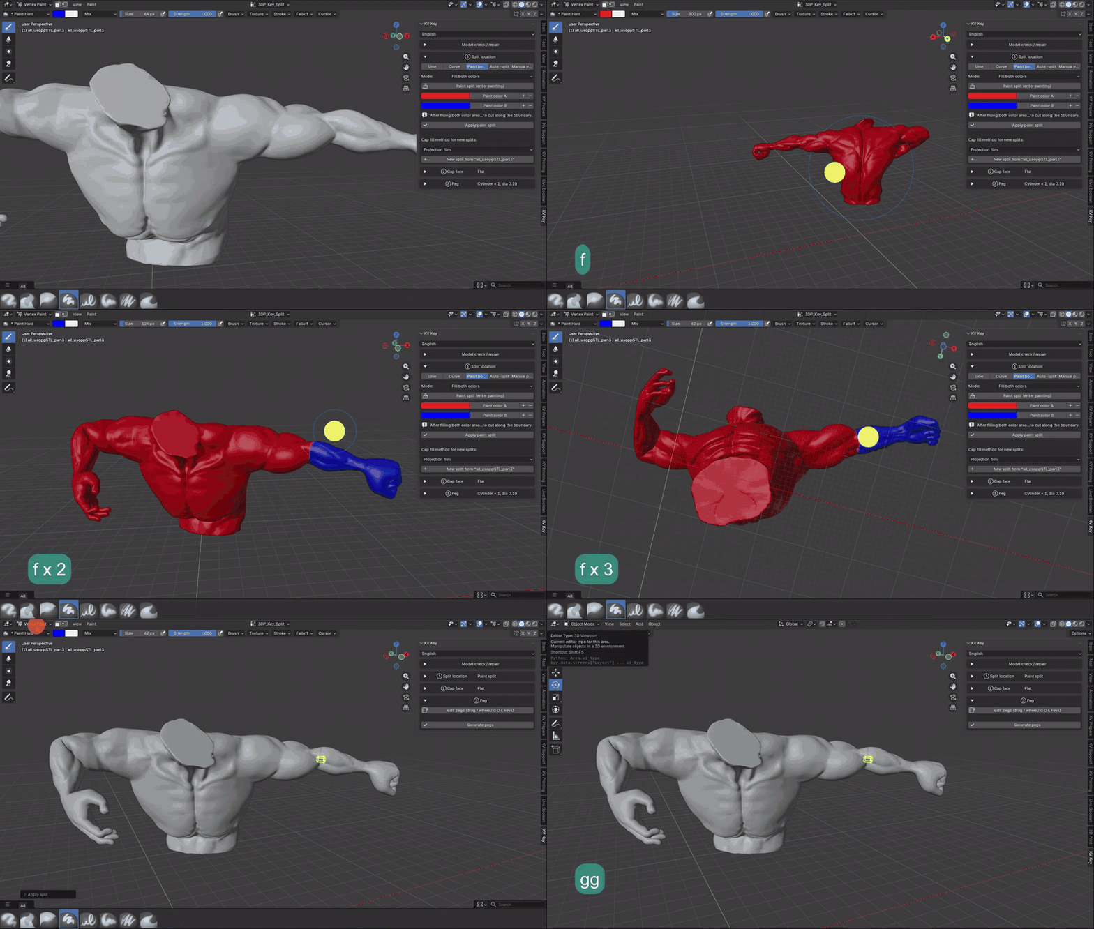
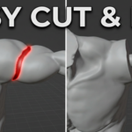
② Outline the seam — paint a single "closed band" along the seam and nothing else; the cut lands on the centerline of the band. The band must go all the way around.

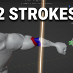
③ Midline of two strokes — just one stroke on each side of the seam; the cut lands on the geodesic midline between them. Least painting, but slower on large models.
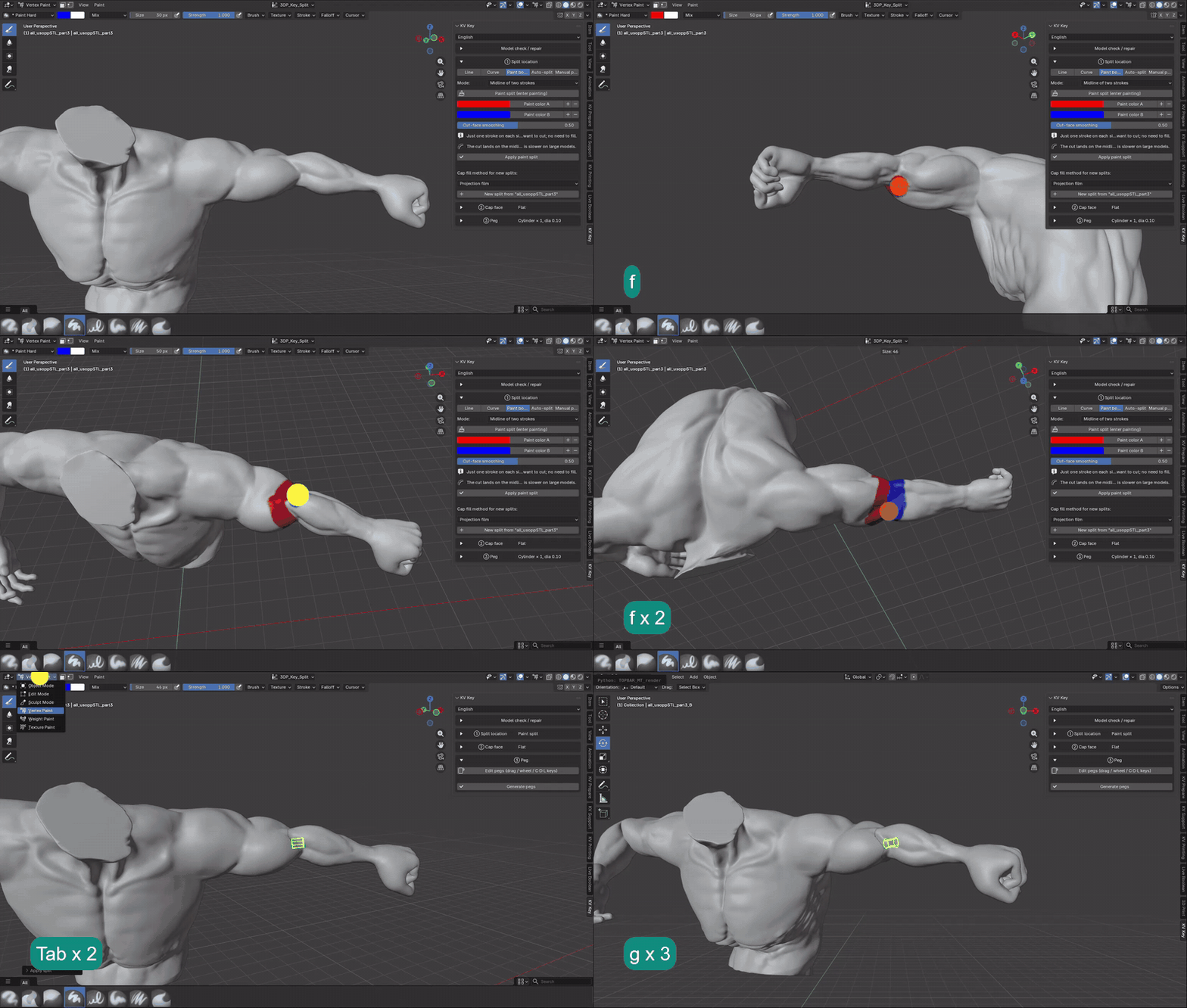
> If the cut face is jagged, raise "Cut-face smoothing" and apply again.
Auto-split
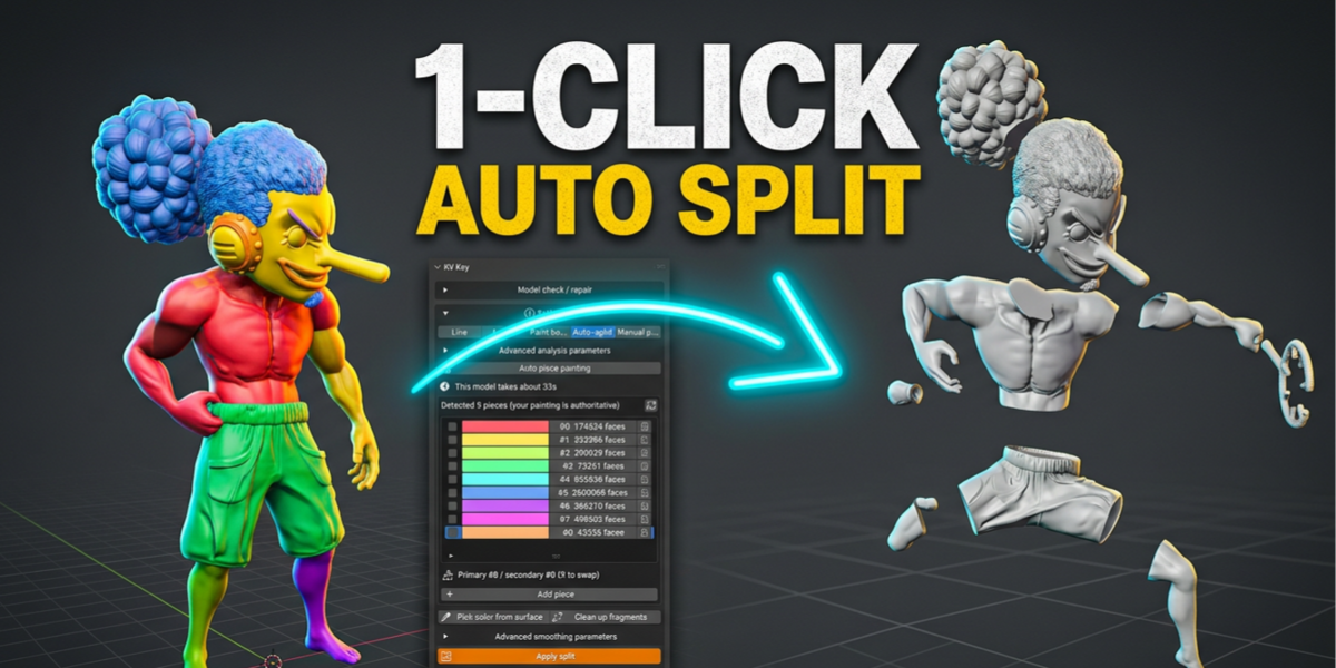
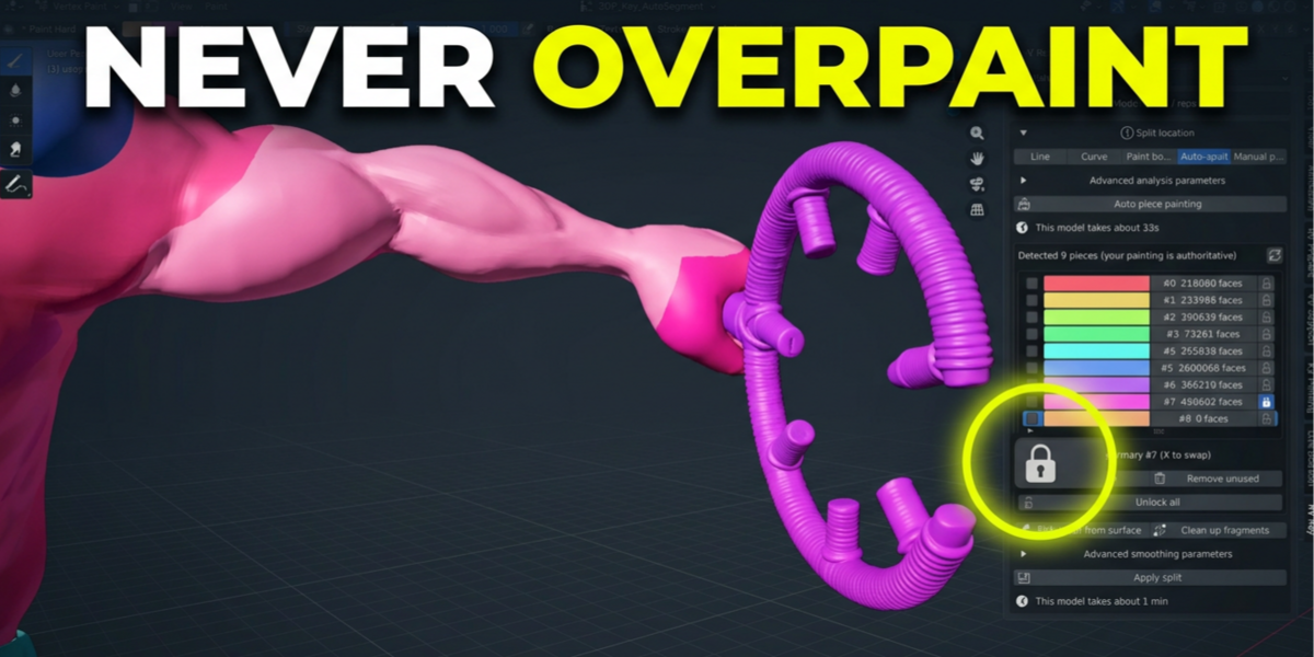
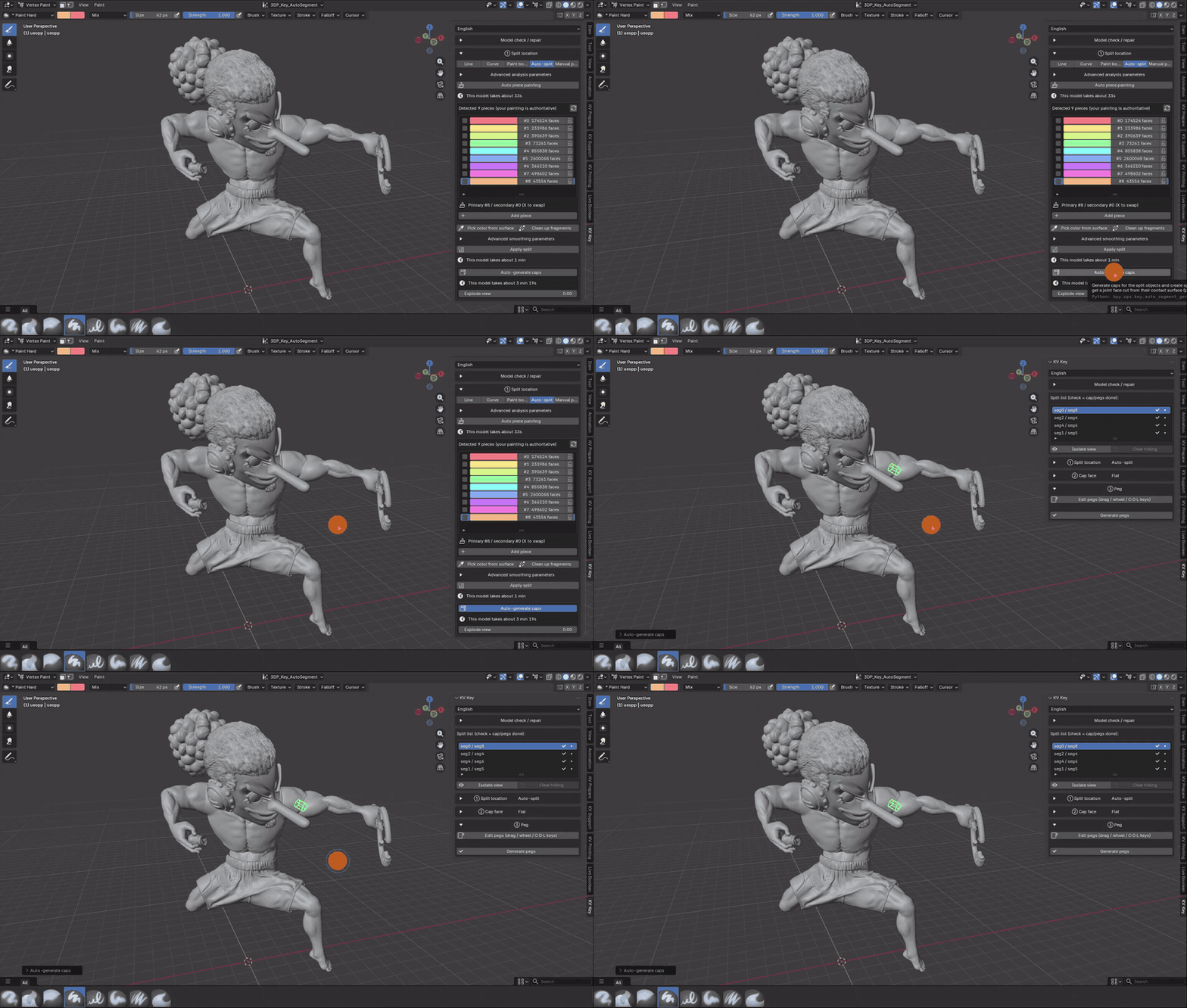
Hand the whole model to the tool: it analyses concavity and hard edges to decide how many pieces to make and paints them. **The colors you see are the pieces** — refine them with a brush until you are happy, then apply.
Step 1: Auto piece painting
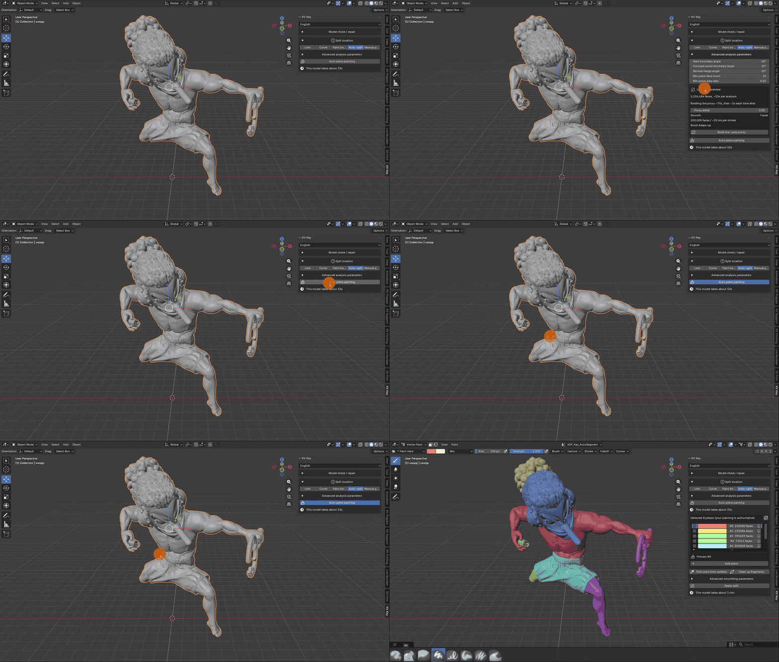
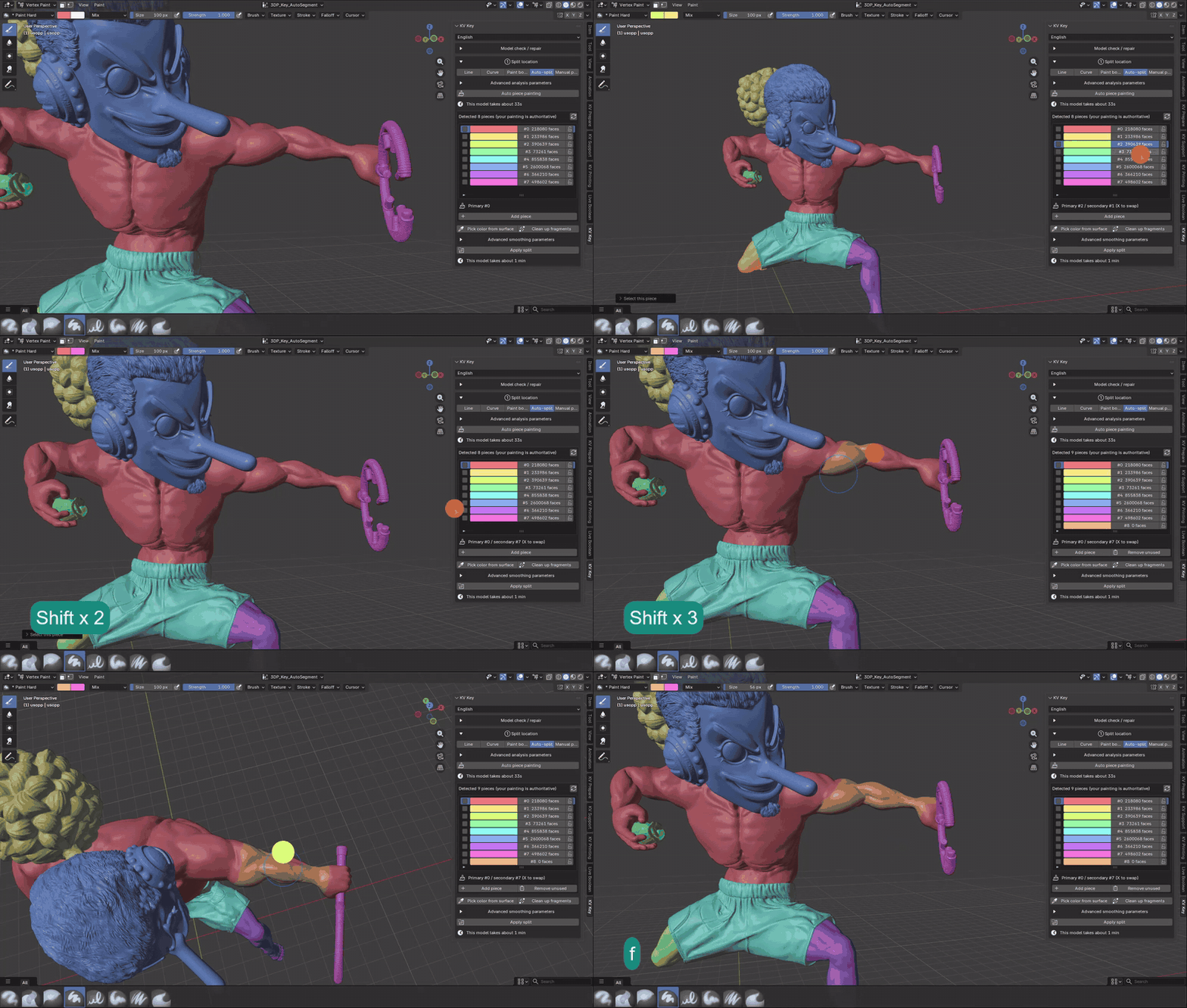
- The panel estimates the runtime first (about 33 s for the 5.2-million-face model shown).
- Advanced analysis parameters: hard boundary angle, concave assist boundary angle, normal merge angle, min piece face count / area ratio. Too many fragments → raise the minimums; pieces not separating → lower the hard boundary angle.
Step 2: Refine the pieces by hand
Each piece is one row (color, face count, lock). Clicking a row makes its color the primary brush color (the previous one becomes secondary, X swaps them), so you can paint corrections straight onto the model.
To add a piece, press "Add piece": a new color is assigned and the brush switches to it — then paint its area.
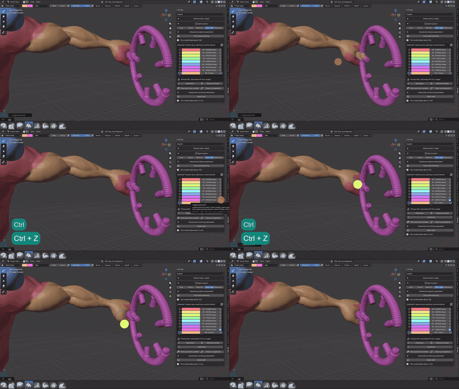
A finished piece can be "locked": painted-over colors are reverted automatically and re-running auto painting leaves it alone.
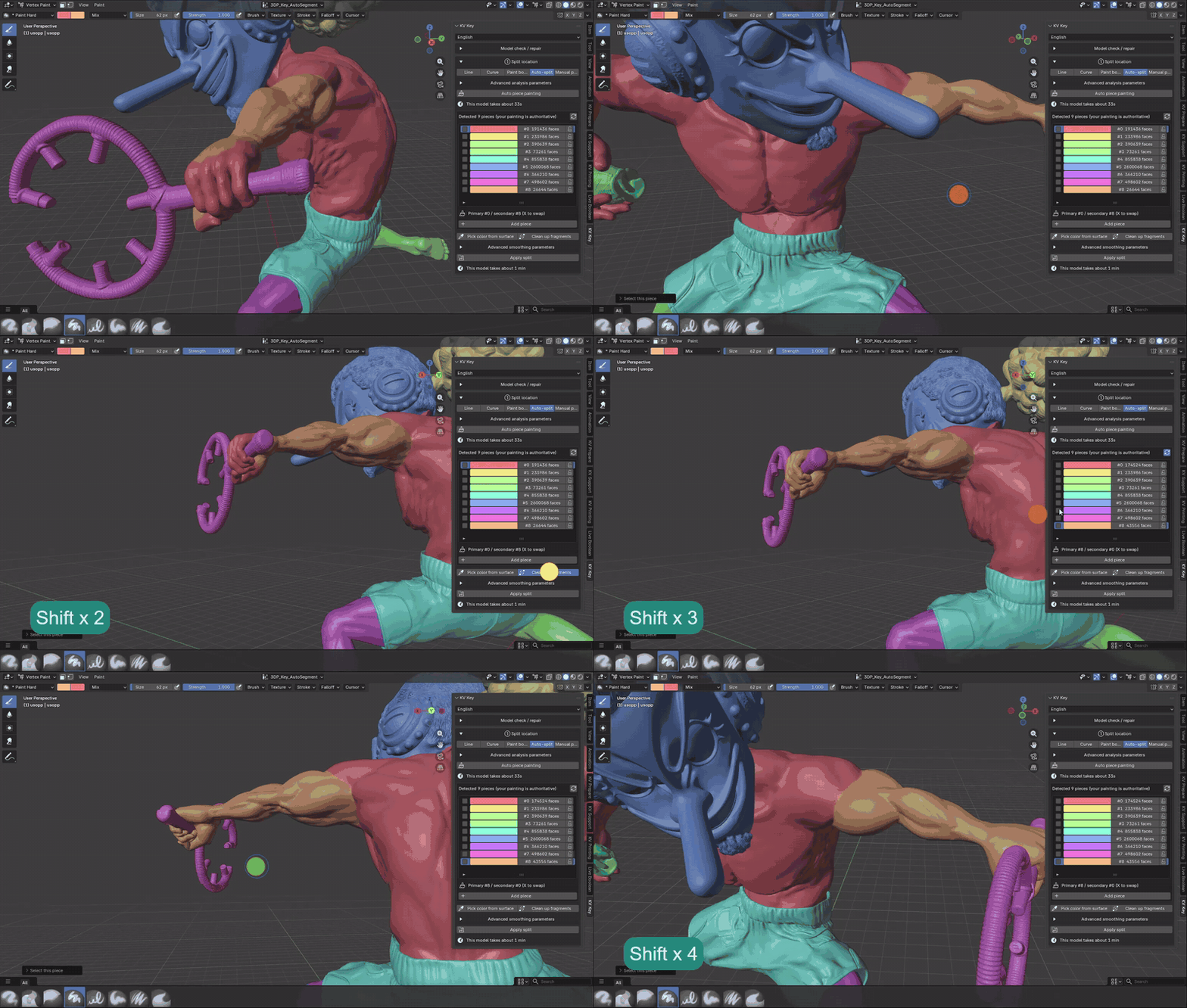
Boundaries often leave scattered specks behind. "Clean up fragments" merges them into their neighbours (locks do not protect against this):
Step 3: Apply split
Turns the painting into N separate objects. Afterwards you get a piece list and an "Explode view" slider to pull the parts apart and inspect them.
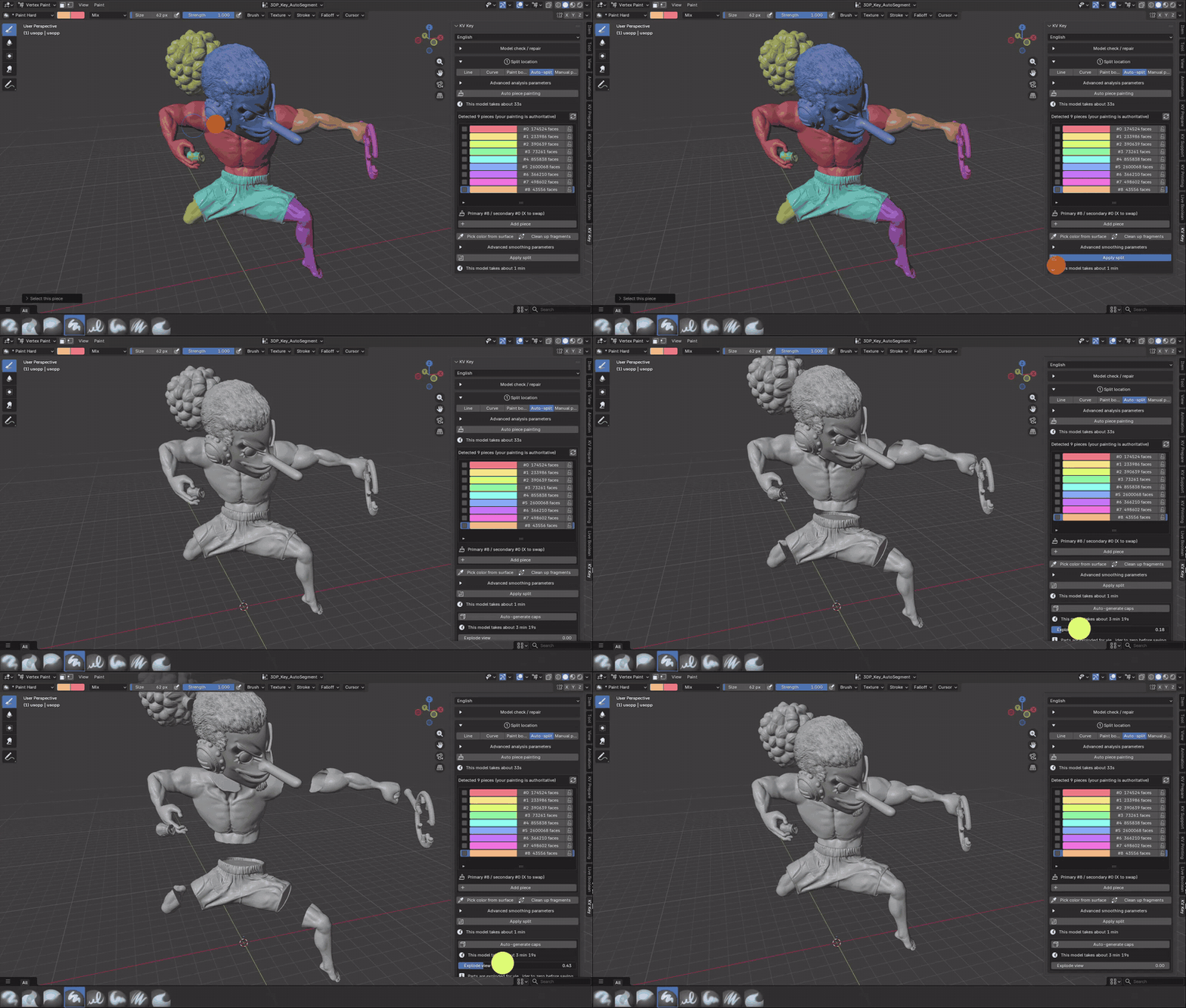
> Explode view is a temporary offset — "set the slider back to zero before saving".
Step 4: Auto-generate caps
Caps every contact area between adjacent pieces at once and creates the matching joints (the split list fills up with `seg0 / seg8`, `seg2 / seg4`, …), ready for ② and ③ one by one.
Manual placement
The model is already two separate parts that sit flush against each other and all you need are pegs — this mode "neither cuts nor caps", it grows male and female pegs directly on the contact area.
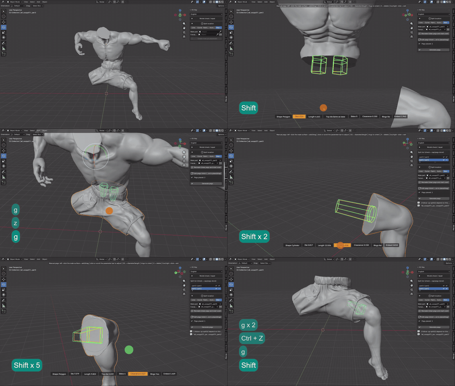
1. Set the "Male part" and the "Female part" (the ⇄ button swaps them).
2. Press "Create".
3. Press "Edit pegs", click "on the male part's surface" to place a peg, drag to move it, D/L to type diameter and length, X to delete.
4. Press "Generate pegs": the male part gets a union with the pegs, the female part a difference (with clearance). Broken geometry is repaired automatically before the boolean.
5. "Recreate (clear pegs and start over)" resets the pair.
> If a peg sits slightly below the female surface or there is a gap between the parts, raise "Embed depth" so the cutter reliably punches through the female surface.
Cap face
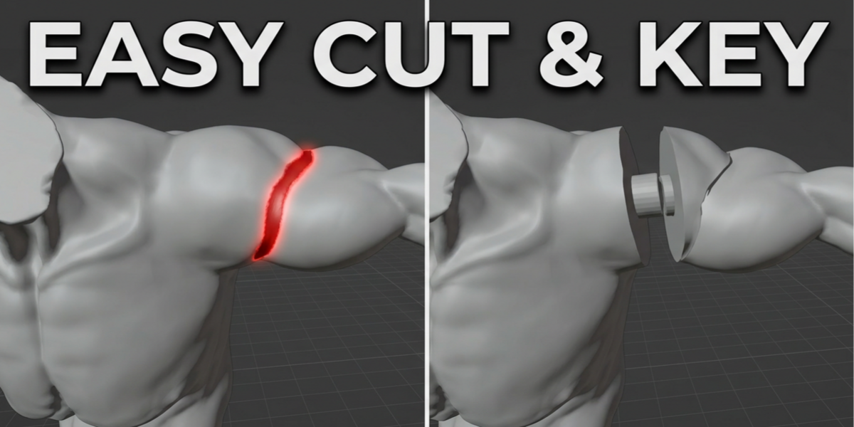
- Flat — The cut is closed with the best-fitting plane — the simple case
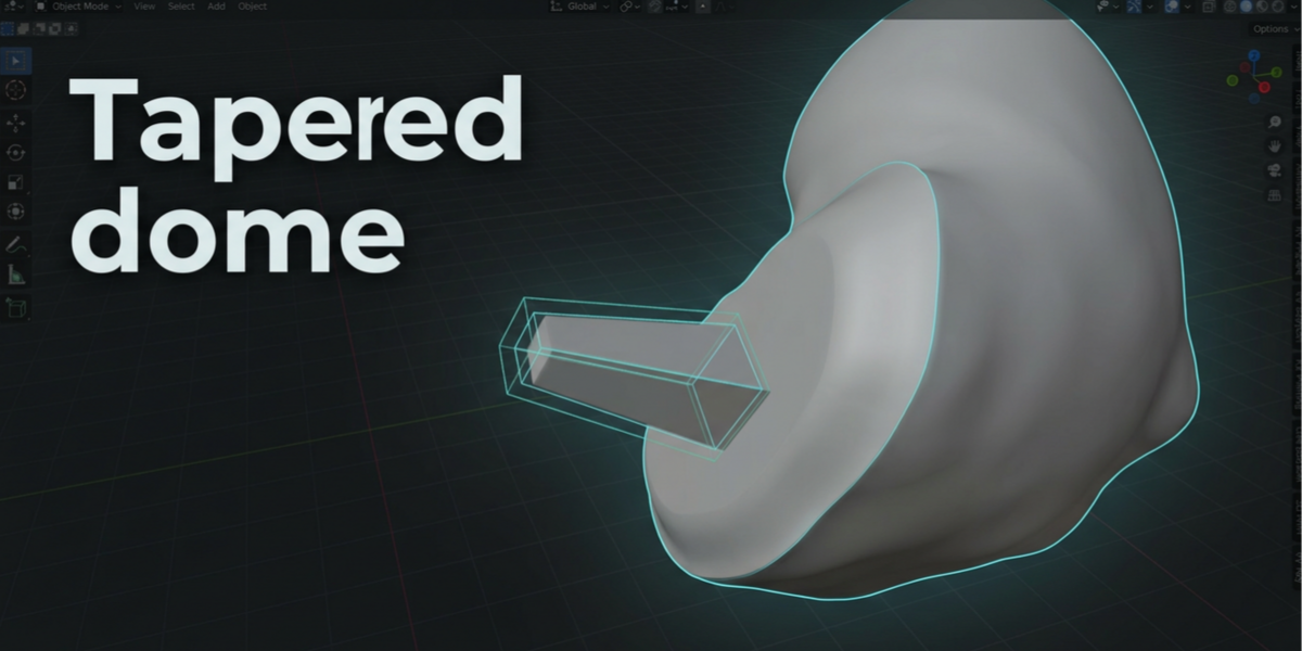
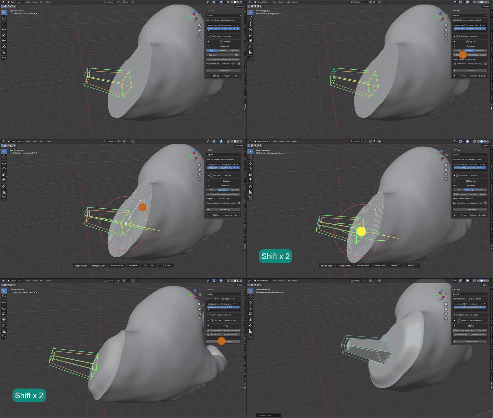
- Tapered dome — The boundary shrinks smoothly toward the centre into a rounded boss that also guides the halves together
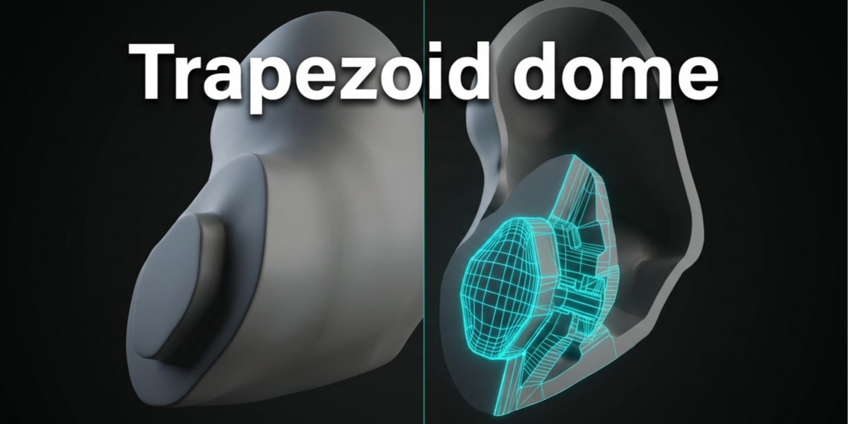
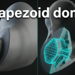
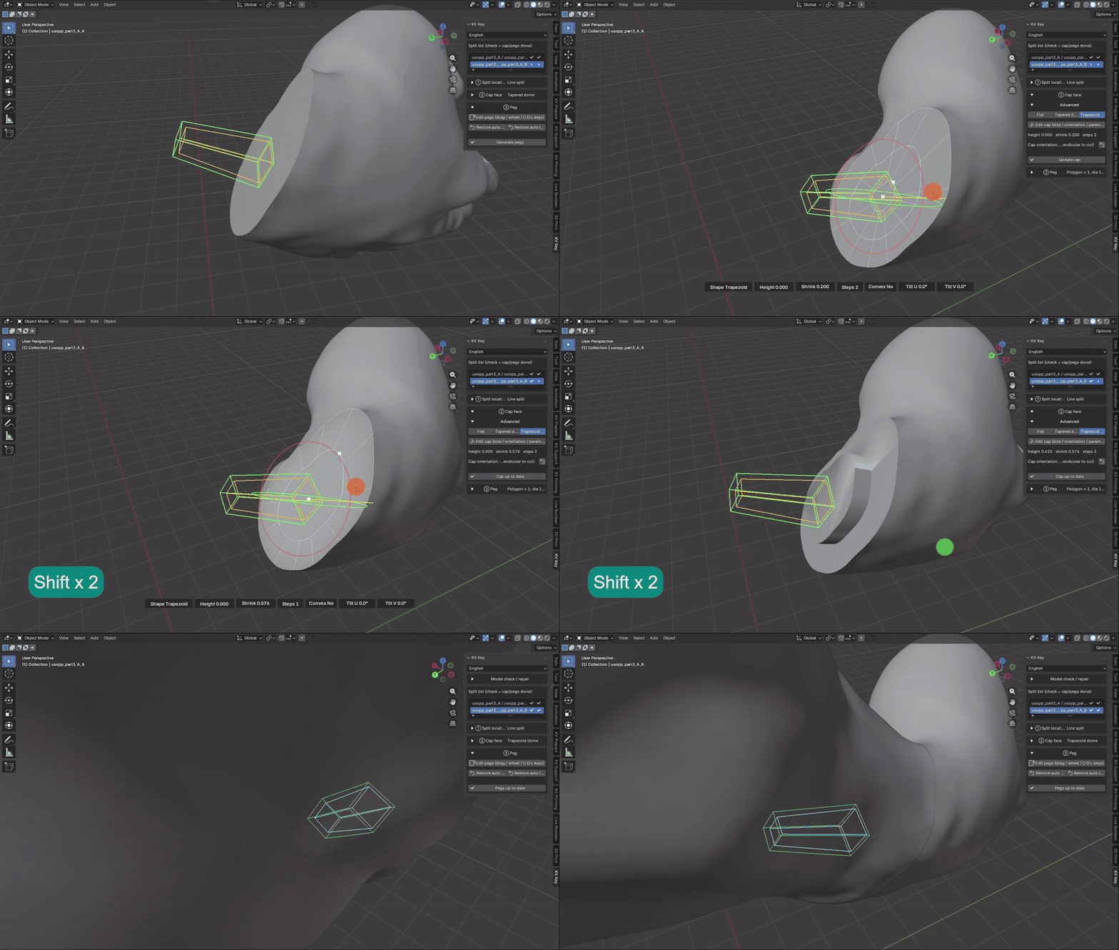
- Trapezoid dome — Stepped shrink-and-lift; the strongest mechanical location
The two sides of a joint are made "complementary automatically" (one convex, one concave) — you only edit side A.
Tapered dome: height and shrink are adjustable.
Trapezoid dome: adds a step count.
Cap fill method
Only relevant for non-planar cuts (curve / paint / auto-split):
Auto - Projection film first, switching to voxel cut only when the cap is detected poking through the surface (default) |
Projection film - Fastest and lightest; may poke out of the surface when the cut is very three-dimensional |
Voxel cut - Cuts along the geodesic midsurface inside the solid — the best-fitting shape, but seconds to tens of seconds per joint |
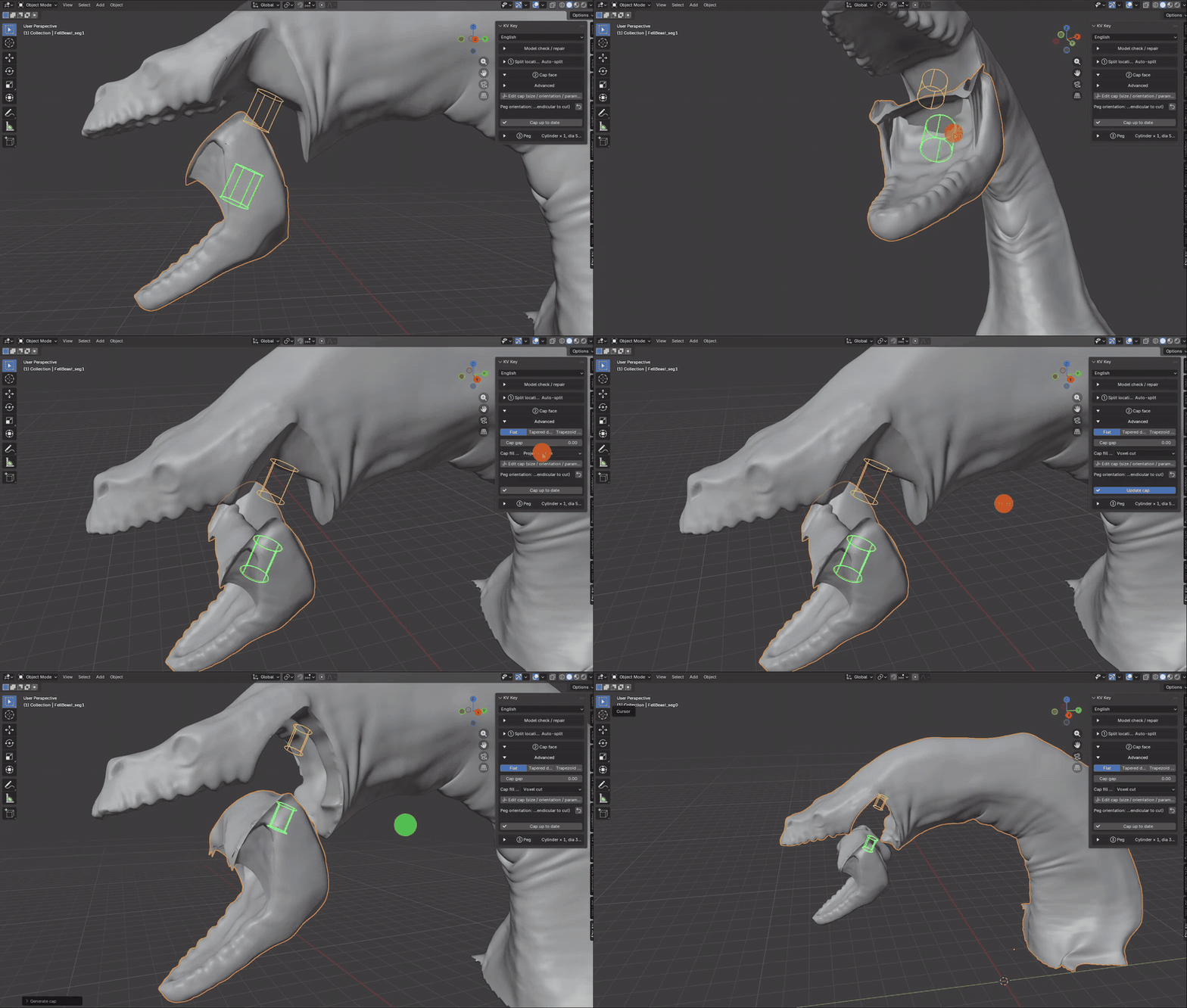
Cap edit mode
- Drag the yellow axis — Height
- Drag the blue axis — Shrink ratio
- Drag the red / green ring — Cap orientation (mating / pull-out direction)
- H / S — Type an exact height / shrink ratio
- Ctrl+wheel or T — Trapezoid step count
- R — Reset orientation
- The parameter bar at the bottom — Hover an item and scroll to adjust; click once to type an exact value
- Esc / right-click — Leave the mode
Press "Update cap" to apply the new parameters; releasing a drag in the viewport applies them automatically
Peg
- Left-drag — Move a peg
- Left-click on empty space — Add a peg there
- X / Del — Delete a peg
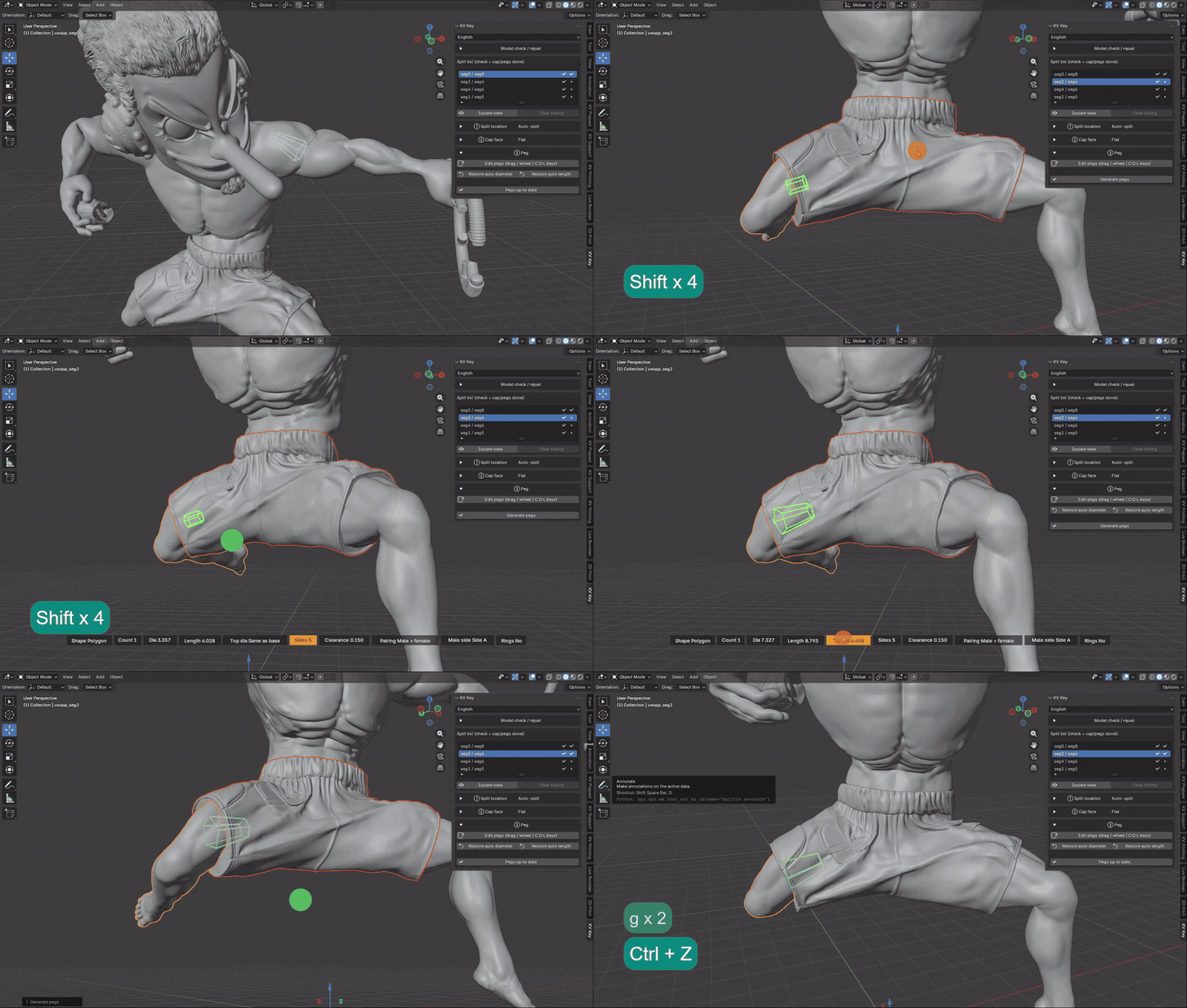
- Ctrl / Shift+wheel — Count / diameter / length
- C / D / L — Type an exact count / diameter / length
- L (on a peg) — Lock it so auto-layout won't move it
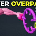
- "Rings" in the parameter bar — Turn it on, then drag the rings to spin around the peg axis or tilt in U/V
- Esc / right-click — Leave the mode
The parameter bar at the bottom - Shape, count, diameter, length, top diameter, sides, ball diameter, clearance, pairing, male side
When the layout looks right, you must press "Generate pegs" — until then it is only a wireframe preview.
Each joint on the model is independent: select it in the split list and generate (the demo does `seg0 / seg8` first, then `seg2 / seg4`):
Peg Shapes and parameters
- Cylinder — Base/top diameter adjustable into a tapered frustum |
- Polygon — Anti-rotation post with 3–8 sides; the top can taper in or flare out |
- Ball — Cylinder with a ball on top; the ball may be wider than the neck and the socket is enlarged to avoid an undercut |
- Dovetail — Undercut key whose cross-section flares along its length — resists pulling apart |
Other parameters you will touch:
- Diameter — when automatic, it is the cap's largest inscribed-circle diameter × the diameter ratio; typing a value locks it, and "Restore auto diameter" hands it back.
- Length — when automatic, diameter × 1.2 (for Ball this is the total length including the ball).
- Clearance — per-side gap between male and female, default "0.15 mm" (0.1–0.2 mm is typical for FDM). This is a print tolerance and "does not scale with the cap".
- Pair mode — one male + one female (direct mating), or two sockets joined by a separate dowel.
- Male side — which part grows the pegs; switching it flips the convex/concave caps accordingly.
> When the panel shows the red "diameter exceeds the limit" warning, this cap cannot fit a peg that thick and "Generate pegs will fail". Reduce the diameter or use a larger cap.
$20
Have questions about this product?
Login to message
| Blender Extension Compatible | Yes |
| Published | about 21 hours ago |
| Blender Version | 4.3 - 5.2 |
| Extension Type | Add-on |
| Render Engine Used | Cycles |
| License | GPL |
Discover more products like this
3d print boolean 3d print joints miniatures joint peg mesh cut keyed joint 3dprint slicer