Smart Loft Curves
 Fares Asem


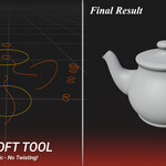
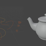
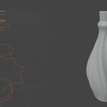
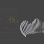
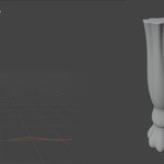
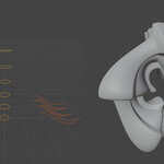
Parameters Description
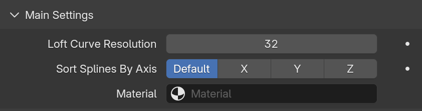
1.Main Settings
Defines the core settings that control the overall behavior and structure of the loft.
Loft Curve Resolution: Controls the resolution of the lofted geometry by resampling the input curves.
Sort Splines By Axis: Defines the axis used to sort the spline order before generating the loft.
Default: Preserves the original spline order as defined by the curve creation sequence.
X / Y / Z: Sorts splines based on their position along the selected axis.
-
Material: Assigns a material directly to the generated geometry. If no material is selected,
the object’s existing material setup won’t be used.
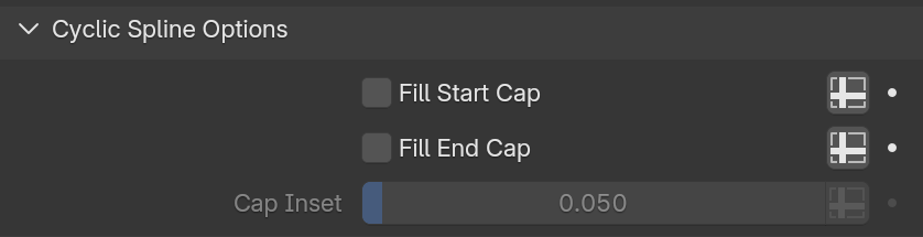
2.Cyclic Spline Options
Controls how start and end caps are generated when working with cyclic splines.
Fill Start Cap: Closes the start of the loft by generating a cap when the spline is cyclic.
Fill End Cap: Closes the end of the loft by generating a cap when the spline is cyclic.
Cap Inset: Controls the inset Thickness of cap faces.
3.Transition Between Splines
Defines how geometry is interpolated and blended between consecutive splines.
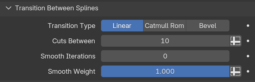
Transition Type
Linear: Creates a straight, uniform transition between splines.
Cuts Between: Controls the number of intermediate cuts generated between splines.
Smooth Iterations: Defines the number of smoothing passes applied to the transition.
Smooth Weight: Controls the strength of the smoothing effect.
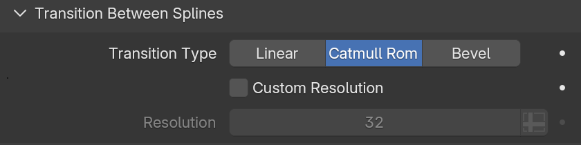
Catmull-Rom: Creates a smooth, interpolated transition using Catmull-Rom spline interpolation.
Custom Resolution: Enables resolution control for the Catmull-Rom transition
Resolution: Defines the number of segments used for the Catmull-Rom transition.
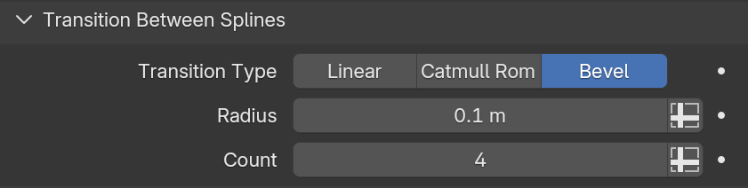
Bevel: Generates a beveled transition with a sharper profile.
Radius: Adjusts the distance from the original.
Count: The number of edge loops added along the bevel’s face.
4.Deform On Curve
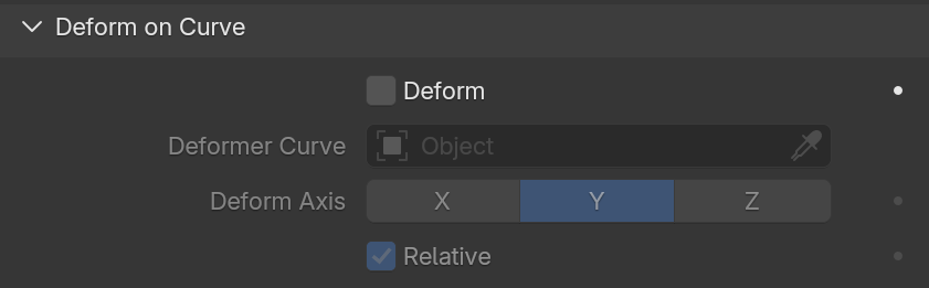
Deforms the generated geometry along a target curve, allowing control over shape flow and direction.
Deform : Enables deformation along the selected curve.
Deformer Curve: Curve you want the geometry to follow.
Deform Direction: The chosen axis is that the curve deforms along.
Relative: When enabled, the geometry snaps directly to the path's origin.
Note: The deformation curve can use its radius to control scaling and its tilt to control rotation along the curve.
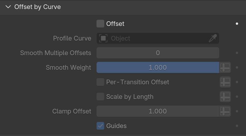
5.Offset by Curve (Advanced Profile Shaping)
Applies a profile-based offset to the loft using a separate curve, enabling advanced shape control.
Offset : Enables profile displacement based on a separate curve.
Profile Curve: Choose a curve to act as the "cross-section" or "depth profile" of the loft.
Smooth Multiple Offsets: Blends the offset effect across multiple splines to avoid sharp transitions.
Smooth Weight: Controls the strength of the smoothing effect.
Per-Transition Offset: Calculates the offset independently for each transition segment.
Scale by Length: Adjusts the offset scale based on the transition length.
Clamp Offset: Limits the maximum offset.
-
Guides: Guide lines to help you visualize the relationship between your source geometry and
the profile curve during the design process.
-
Note: Offset is evaluated in spline space, where Z defines the offset direction, X follows spline flow,
and Y preserves spline positioning.
Note: When multiple splines are present, the offset follows the relative spacing between splines.
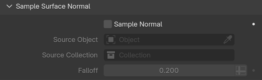
6.Sample Surface Normal (Surface Interaction)
Samples the nearest surface normal and applies them to the loft geometry.
Sample Normal: Assigns the nearest surface normal to the loft geometry.
Object / Collection: Object or collection used to sample surface normal.
Falloff: Controls the influence radius of the normal sampling
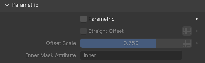
7. Parametric (Architectural Tools)
Provides parametric controls for generating precise frames, moldings, and architectural details.
Parametric: Enables parametric geometry generation.
Straight Offset: Keeps the offset straight, without curvature interpolation.
Offset Scale: Controls the thickness or depth of the parametric offset.
-
Inner Mask Attribute: Outputs a named attribute for the inner regions of the mesh,
useful for shading and further node processing.
8. UV Map (Final Texturing Control)
Generates and assigns UV coordinates to the loft geometry.
UV Name: Set a custom name for your UV map attribute.
UV Type:
Generated: Uses the generated UV grid based on the loft geometry.
Box Project: Generates a box-style UV projection based on object orientation.

Notes:
-
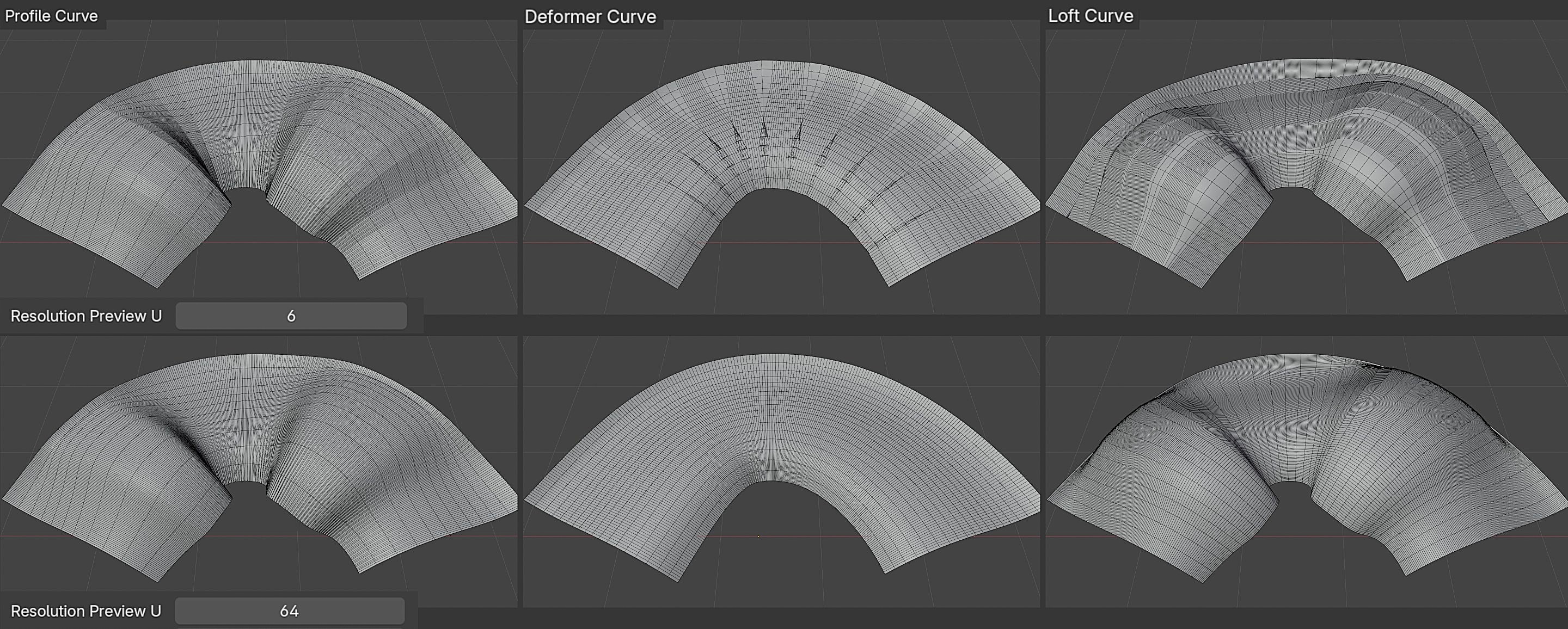
Curve resolution affects the overall smoothness of the geometry, The default value is 12;
increasing it will result in a smoother appearance.
Tips:
-
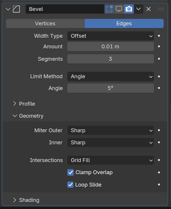
If the Bevel modifier does not work as expected on parametric loft results,
make sure Clamp Overlap is disabled in the Bevel modifier’s Geometry settings.
Have questions about this product?
Login to message
| Sales | 10+ |
| Dev Fund Contributor | |
| Published | 8 months ago |
| Blender Version | 5.0 |
| Render Engine Used | Cycles |
| License | GPL |
Discover more products like this
auto sort uv mapping modifier Generator loft tool ArchViz parametric modeling procedural curve hard surface geometry nodes