Entropy Designer Engine 2.3.0
 Ritual Studio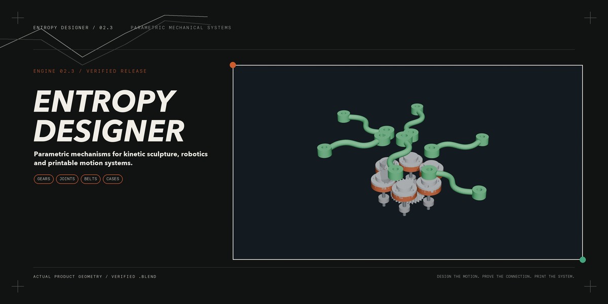


Entropy Designer 2.3 User Documentation
Entropy Designer is a Blender mechanism-design extension for kinetic sculpture,
robotic and animatronic joints, printable transmissions, and optional energy
harvesting. It keeps related dimensions, mechanical connections, animation, and
fabrication checks in one guided workflow.
The default workspace is **Mechanism + Robot Joints**. The turbine, generator,
wind, and electrical tools are optional modules rather than the product's main
workflow.
## Included with release 2.3
- Entropy Designer 2.3 add-on ZIP.
- `product.blend`, containing the verified T2.5 synchronous-drive example.
- This user documentation and the shorter Quick Start.
- A 2.3 changelog describing timing-drive and D-flat corrections.
- Three 4K timing-drive reference images.
- Marketplace examples created from real generated Blender geometry.
## Install the add-on
1. Open Blender 4.3 or newer.
2. Open **Edit > Preferences > Get Extensions**.
3. Choose **Install from Disk** and select `entropy_designer-2.3.0.zip`.
4. Enable **Entropy Designer**.
5. Return to the 3D Viewport, open the sidebar with **N**, and select
   **Entropy**.
The release was tested in Blender 4.5.1 LTS. Start with a copy of your project
until your printer, materials, purchased components, and preferred tolerances
have been calibrated.
## Open the product demo
Open `product.blend` after enabling Entropy Designer. The scene contains a
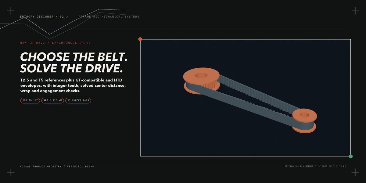
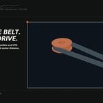
generated 28-tooth to 14-tooth T2.5 timing drive using a 90-tooth, 225 mm pitch
length belt and a solved 86.069678 mm center distance.
In Blender's Text Editor, read these embedded blocks:
- `README_FIRST`
- `QUICK_START_2_3`
- `CHANGELOG_2_3`
- `ENTROPY_DOCUMENTATION`
The visible meshes can still be inspected when the add-on is disabled, but the
guided parameters, regeneration, checks, and export operators require the
add-on.
## The guided workflow
### Start and configure
Choose **Basic** control level for the essential workflow. Choose **Design** to
expose dimensions, loads, and manufacturing choices. Use **Expert** when you
need detailed clearances, solver controls, diagnostics, or specialist energy
settings.
Select a scenario starter, then edit its values. A starter does not silently
replace geometry; press **Generate / Update Assembly** when you are ready to
build or refresh the mechanism.
Useful starters include:
| Starter | Use it for |
| --- | --- |
| Kinetic Flower | One central drive with several fixed-axis sculpture outputs |
| Robotic Joint | Compact planetary reduction and an output flange |
| Quadruped or Biped Joint | Editable limb-joint load and motion starting points |
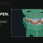
| Pan / Tilt | Limited-angle animatronic or camera-style rotary axes |
| Direct Test | Learning generation, connection checks, and animation |
| Wind Generator | Optional turbine-to-generator speed conversion |
### Follow the numbered panels
1. **Actuator / Generator Interface** — choose the motor role, shaft, pilot,
   mounting pattern, and verified performance data.
2. **Reducer + Kinetic Output** — choose direct, spur gear, timing belt, crank,
   or stacked planetary motion.
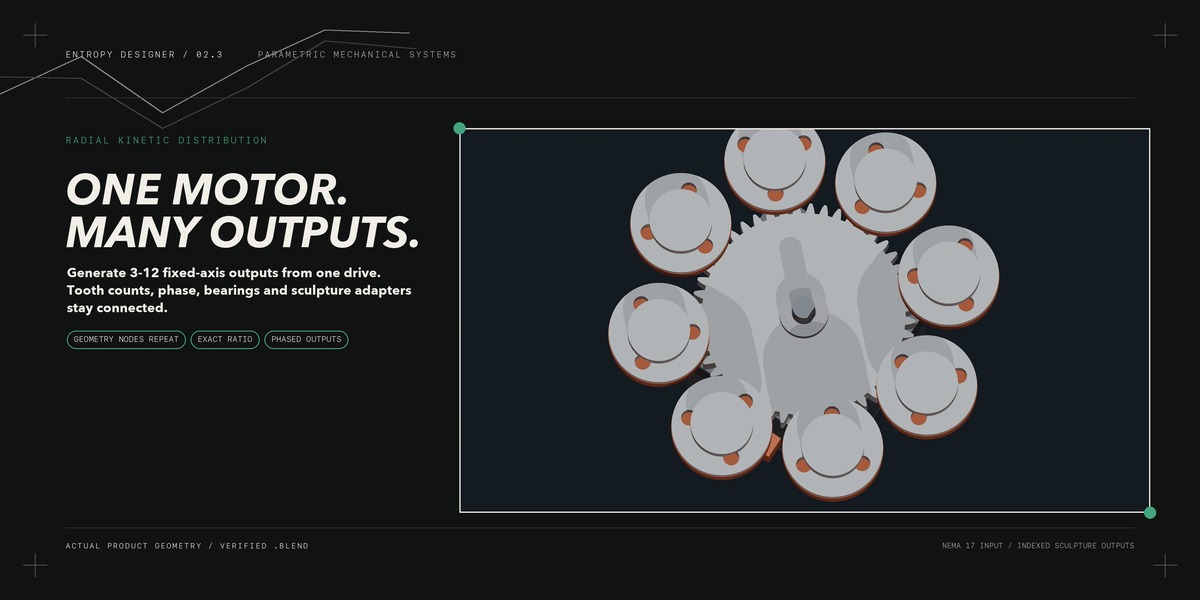
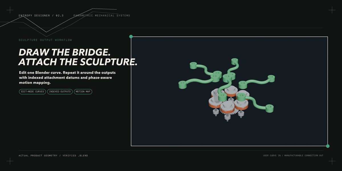
3. **Radial Multi-Output** — configure one central gear and 3–12 fixed-axis
   output rotors for kinetic sculpture.
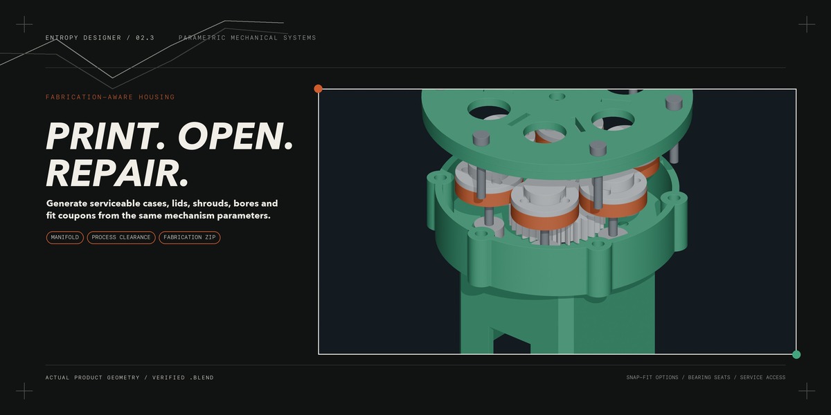
4. **Housing + Print Fits** — generate the service case, lid, clearances,
   fastener envelopes, bearing seats, and calibration coupons.
5. **Motion, Verification + Export** — connect targets, check the mechanical
   chain, preview motion, run Preflight, and build the fabrication package.
6. **Joint Load + Engineering** — screen joint torque, speed, tooth load,
   payload, inertia, and service factor.
7. **Optional Turbine Input** and **Optional Wind + Solver Handoff** — use only
   when the project includes energy harvesting or wind screening.
## Generate and regenerate safely
Press **Generate / Update Assembly** after changing any geometry-driving value.
Entropy replaces only generated objects carrying the current design identity;
unrelated user objects are left in place.
A parameter change makes the generated assembly stale. While stale, animation,
collision checking, and fabrication export remain blocked. Regenerate first so
the meshes, datums, metadata, and motion relationships describe the same design.
Use **Show Datums** and **Focus Entropy Component** to inspect shafts, axes,
pitch centers, bearing locations, output interfaces, and attachment points.
## Timing drives in version 2.3
### Choose the belt family
- **T2.5** and **T5** generate published-dimension reference grooves for
  prototyping and calibration.
- **2 mm GT-Compatible**, **HTD 3M**, and **HTD 5M** generate pitch-accurate
  layout envelopes. Replace their reference pulley teeth with matching supplier
  CAD before final fabrication.
- **Custom Smooth** remains available for an unsynchronized belt envelope.
### Solve from a real integer belt
1. Choose the driver and driven pulley tooth counts.
2. Choose the integer belt tooth count.
3. Enter the belt axial width and pulley side clearance.
4. Select **Solve from Belt**.
5. Read the derived ratio, pulley pitch diameters, pitch length, center distance,
   wrap angles, and engaged teeth.
6. Generate the assembly and run **Check Connections**.
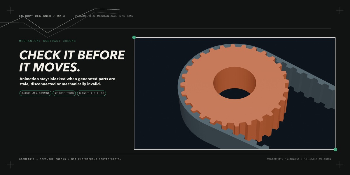
For a standard synchronous belt, pitch diameter is derived from pitch and tooth
count; it is not an independent visual-size slider. **Manual Center** preserves
your entered shaft spacing but fails the mechanical gate if the resulting path
does not match the selected integer belt length.
Entropy rejects overlapping pulley envelopes, incompatible profiles, incorrect
pitch length, too few pulley teeth, fewer than six engaged teeth, broken
parenting, axial misalignment, and incorrect rest phase before animation.
The generated belt is a spatial reference for a purchased reinforced belt. Do
not treat a rigid printed belt as equivalent. Provide a real tensioning method
and check the selected manufacturer's current ratings and drawings.
## Radial multi-output sculpture systems
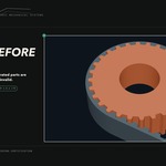
Enable **Radial Stepper Distributor** to drive 3–12 fixed output axes from one
central external spur gear. The outer axes do not orbit, so this is a radial
compound gear mechanism rather than a planetary train.
The workflow derives:
- center radius from module and both tooth counts;
- output speed and opposite rotation direction;
- available torque per branch;
- adjacent gear and flange clearance;
- involute contact ratio and a first-order tooth-load screen; and
- output datums for bridges, adapters, and sculpture objects.
Use **Geometry Nodes Repeat** for the live procedural pattern. Use **Bake Repeat
Zone to Parts** when individually selectable gear meshes are needed for
inspection or export.
To connect sculpture objects directly, select up to the configured output count
and choose **Connect Selected to Radial Outputs**. Each object's origin is moved
to its indexed attachment datum and follows the full output transform.
## Stacked planetary joints
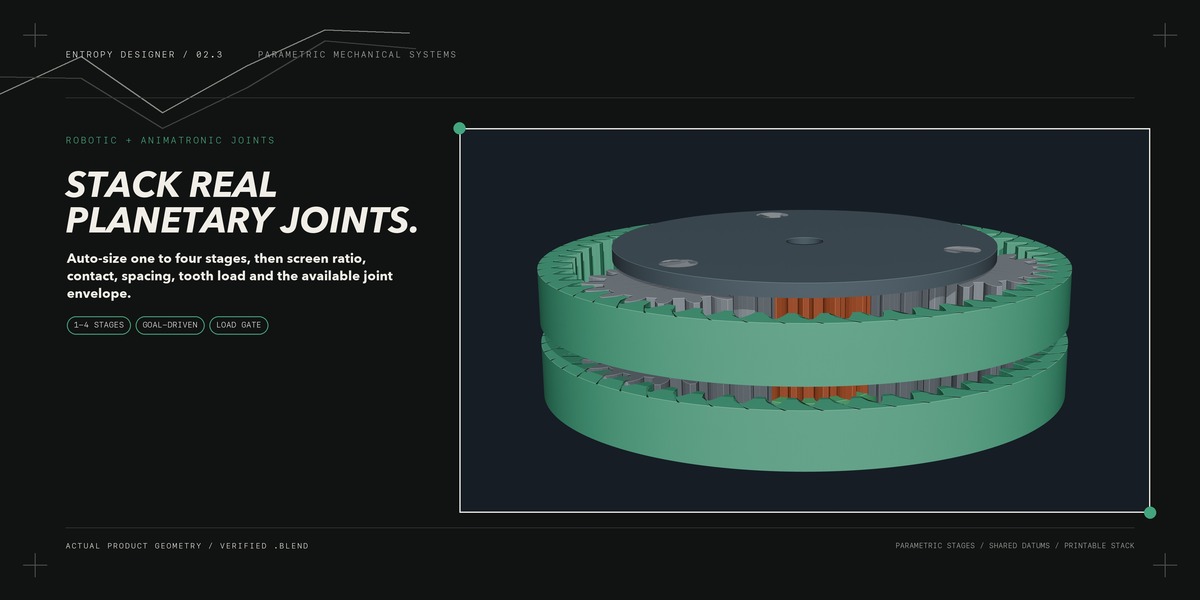
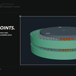
The planetary workflow supports one to four coaxial stages. **Auto Size
Planetary** searches tooth combinations for the requested ratio and maximum
diameter, then applies the normal assembly, spacing, contact, tooth-load, and
envelope checks.
The generated tooth sets enforce the coaxial relationship and equal planet
spacing. The joint screen also considers ring wall, adjacent planet clearance,
stage height, fixed-member selection, motor speed, payload torque, link inertia,
and the requested service factor.
Robot starters are editable load cases, not proof that one printed reducer can
support a complete robot. Configure each joint separately and include bearings,
hard stops, encoders, wiring, thermal limits, brakes, and emergency behavior in
the larger system design.
## Use a drawn curve as a mechanical bridge
1. Add or select one open POLY or Bezier curve.
2. In Edit Mode, place the first point at the local output-shaft datum.
3. Place the last point at the intended sculpture pin or connection datum.
4. Enable **Curve-Authored Output Bridges**.
5. Choose **Radial Endpoints** to rotate the endpoint outward around every
   branch, or **As Drawn** to preserve the local curve shape.
6. Generate again, inspect each layer, and run the full-cycle interference check.
The bridge follows object scale and the bridge size multiplier. Editing curve
points or handles marks the generated design stale. A passing geometric screen
does not prove deflection, fatigue, pin shear, bearing life, or dynamic balance.
## Printable housing and real fits
The distributor housing derives its gear cavity, motor sleeve, pilot opening,
mounting holes, output exits, insert bosses, cable exit, service lid, locating
skirt, and ventilation from the same mechanism parameters.
Set the manufacturing profile before finalizing fits. FDM, durable resin, SLS
nylon, and MJF nylon profiles provide editable starting allowances; they are not
printer certificates. Print the included shaft, bearing, snap-fit, and backlash
coupons before committing to the complete housing.
Use **Exploded View** to inspect service access. Verify the actual motor
connector, cable bend radius, screw head, insert dimensions, bearing seat, and
tool access before printing.
## Connect, verify, and animate
Use this order after every important design change:
1. **Generate / Update Assembly**
2. **Audit Assembly Alignment**
3. **Analyze Mechanical Connections**
4. **Check Full Motion Cycle**
5. **Run Production Preflight**
6. **Animate Mechanism**
Animation is a kinematic preview. It remains blocked when required parts are
missing, stale, disconnected, misaligned, incorrectly parented, overloaded by
the selected reduced-order screen, or incompatible with the active drive
contract.
The full-cycle checker samples evaluated meshes across one cycle. Increase the
sample count for fast or complex motion. It is not continuous collision
detection or contact dynamics; rotate the physical assembly by hand before
powering it.
## Fabrication package
After Preflight and validation, choose **Build Fabrication Package**. The export
can include:
- centered millimetre STL files for printable parts;
- reference STL files for purchased or separately fabricated items;
- `BOM.csv`;
- design, validation, alignment, interference, and motion-map records;
- assembly instructions;
- shaft, bearing, snap-fit, and gear-backlash coupons; and
- a fabrication manifest with triangle and file-byte checks.
Inspect every STL in the slicer and choose orientation and supports for the
actual process. Entropy does not convert polygon meshes into STEP because that
would imply B-rep precision the generated Blender meshes do not contain.
## Troubleshooting
### The assembly will not animate
Read the most recent connection and Preflight messages. Regenerate if the design
is stale. Restore missing parents or parts, correct belt length and engagement,
fix datum alignment, or reduce an overloaded joint before trying again.
### Belt width changes but the pulley appears unchanged
In the 2.3 standard timing workflow, belt width controls the belt reference and
pulley face width equals belt width plus twice the side clearance. Regenerate
the assembly and inspect the axial direction. Pulley pitch diameter is controlled
by pitch and tooth count, not belt width.
### The generated housing or output appears displaced
Run **Audit Assembly Alignment** and focus the reported component. Confirm the
current design identity, regenerate, and avoid manually moving generated parts.
Move the parent design or use the intended placement controls instead.
### My custom motor does not match the NEMA 17 preview
The built-in NEMA 17 options are interface envelopes. Use **Custom Verified
Actuator** and enter the purchased motor's measured or manufacturer dimensions,
shaft details, and performance data for a hardware release.
### A curve bridge does not update
Confirm it is an open POLY or Bezier curve, that the correct curve is selected in
the Entropy controls, and that it has at least two usable points. Regenerate after
every Edit Mode change.
## Engineering scope and responsibility
Entropy Designer supplies parameterized Blender geometry, dimensional records,
kinematic relationships, mesh checks, and reduced-order mechanical screens. It
is not certified CAD, FEA, CFD, fatigue qualification, electrical certification,
or a substitute for physical guarding and progressive hardware tests.
Before real operation, verify the purchased motor, belts, bearings, fasteners,
materials, printer calibration, tolerance stack, lubrication, balance, thermal
behavior, shaft retention, cable routing, loads, emergency limits, and local
safety requirements.
$10
 Included
Includes 12 months of
- Support from Ritual Studio
- Product updates
Extend this product’s Support Period +12 months: 50% of product price
Have questions before purchasing?
Login to message
| Published | 6 days ago |
| Blender Version | 4.3 - 5.1 |
| Render Engine Used | Cycles |
| Misc Data | Manifold-Mesh, Rigged, Animated |
| License | GPL |