Flaxflow - Motion Tracking & Geometry Toolkit
 Axel Olsson
in VSE
Axel Olsson
in VSE

FlaxFlow Addon Overview
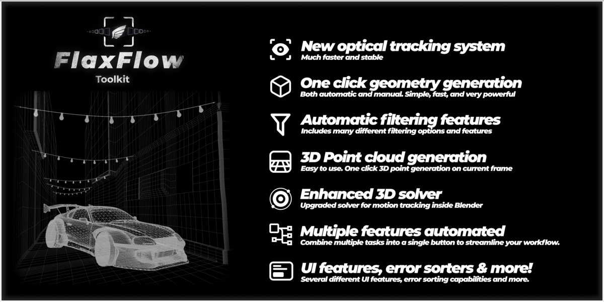
The FlaxFlow addon is a camera tracking and geometry toolkit designed to streamline the VFX workflow in Blender. It offers a range of features that accelerate common tasks involved in motion tracking and geometry setup.
This documentation provides an explanation of each feature. For further assistance or specific questions, feel free to contact me directly on Blender Market.
If you have any feature requests, you're also welcome to reach out via Blender Market, I may include your suggestions in future updates.
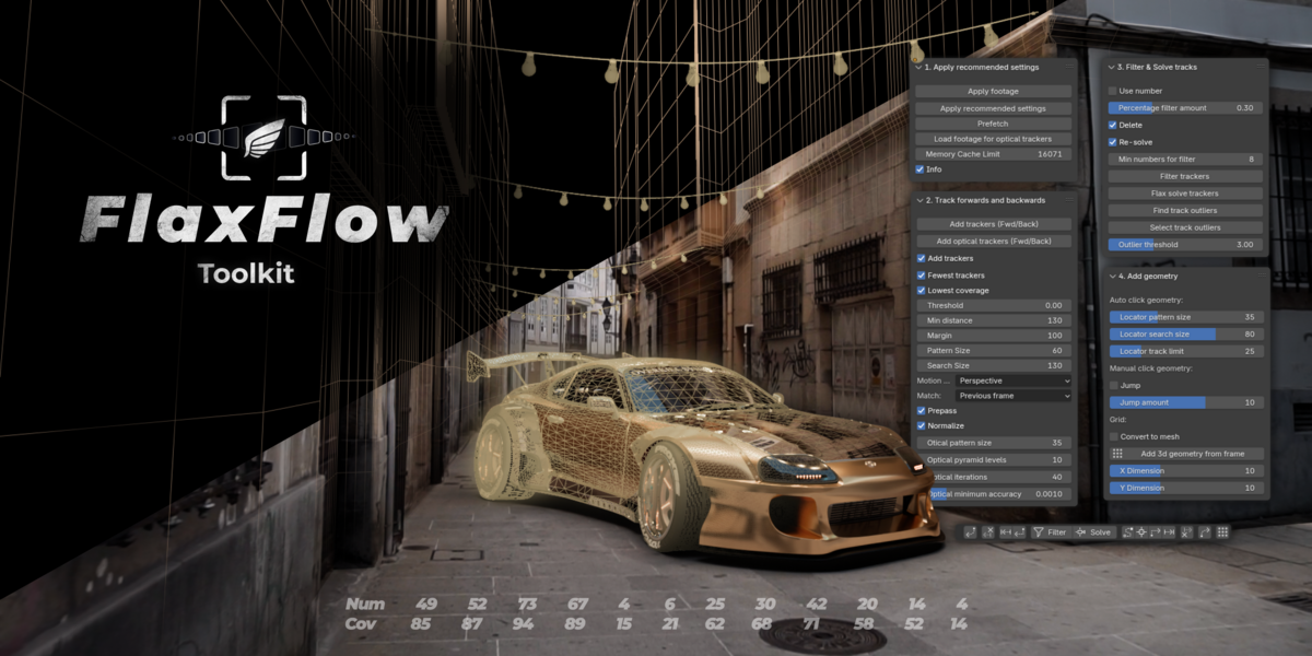
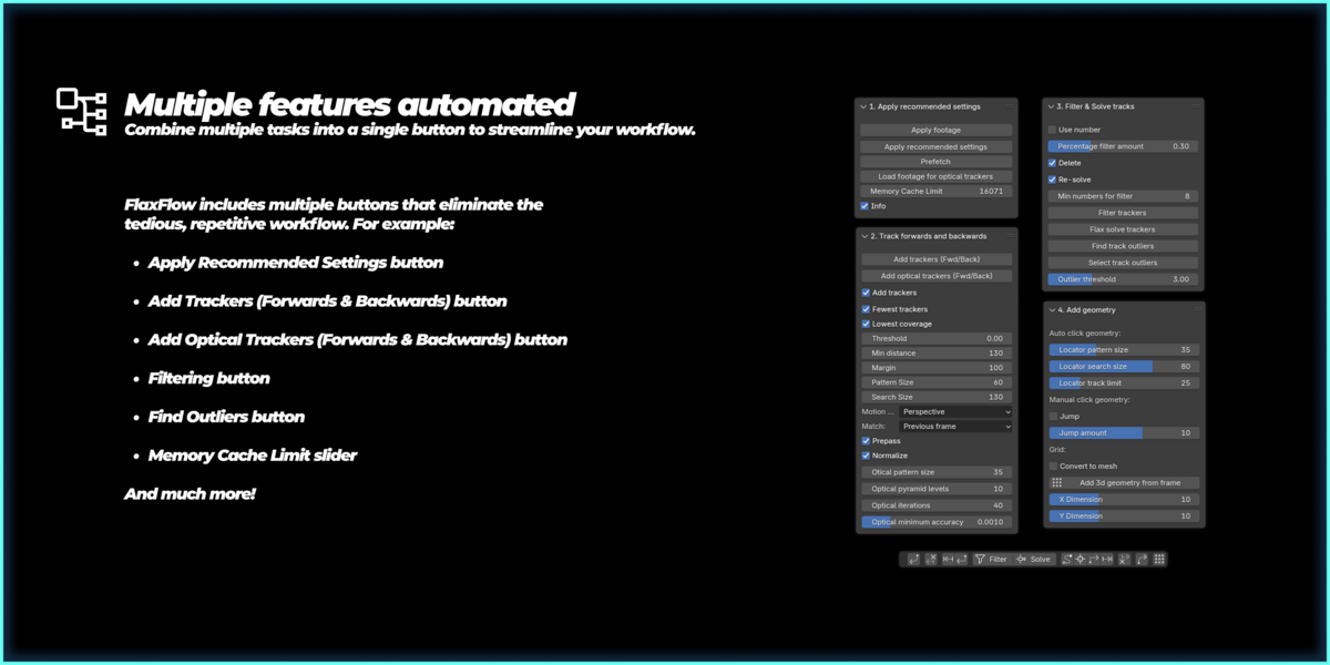
The FlaxFlow addon is organized into four panels, all located in the same place: the left-side panel within Blender's Motion Tracking workspace (VFX → Motion Tracking → FlaxFlow).
The panels are as follows:
-
Apply Recommended Settings
-
Track Forwards and Backwards
-
Filter & Solve Tracks
-
Add Geometry
Each panel and its features will be explained in detail in the sections below.
1. Apply recommended settings panel
Use Current Footage: Sets the currently loaded footage as the active source and saves its folder path, allowing the optical flow trackers to reference the correct footage. This is very important skipping this step will prevent the optical trackers from knowing which footage to track.
Set Scene Frames: Sets the scene's start and end frames to match the clip's start frame and duration. This prevents trackers from entering areas without footage, which could cause errors.
Apply Recommended Settings: Applies the recommended tracking settings, including optimal pattern size, search size, solving parameters, clip settings, and more. Using this option often significantly reduces overall loading time. 
Prefetch: Loads the currently active footage into memory, same as Blender’s regular prefetch function. Highly recommended, as it helps speed up overall tracking performance.
Load Footage for Optical Trackers: Uses the footage path set by "Use Current Footage" to load the footage into the optical trackers. This process may take 5–15 seconds depending on the footage, during which Blender may appear frozen or display a white screen—this is expected behavior. (Note: If you don't click this button manually, the addon will automatically load the footage into the optical trackers the first time you use them.)
Memory Cache Limit: A shortcut to the settings that provides easier access to the memory cache limit. Increasing this value allows Blender to prefetch more footage.
2. Track forwards and backwards
Track (Fwd/Back) or Add Trackers (Fwd/Back): This is the primary button for working with Blender’s native trackers. It uses Blender's built-in tracking algorithm and extends its functionality based on the options enabled in the Detect Features Settings panel below.
For example, if both Add Trackers and Fewest Trackers are enabled, the addon will automatically:
-
Find the frame with the fewest existing trackers
-
Detect features
-
Add new trackers
-
Track them forward
-
Track them backward
-
Return to the original frame
All these steps might seem like a lot, but that’s the whole point, to reduce the number of clicks required and automate the process.
Note: The button label changes depending on whether Add Trackers is enabled. If disabled, it appears as Track (Fwd/Back); if enabled, it appears as Add Trackers (Fwd/Back). This button is also available in the bottom center panel.



Optical Track (Fwd/Back) or Add Optical Trackers (Fwd/Back):
This is the optical equivalent of the Track (Fwd/Back) or Add Trackers (Fwd/Back) button. Its behavior is also determined by the options selected in the Detect Features Settings panel.
For example, if both Add Trackers and Lowest Coverage are enabled, the following steps will be performed automatically:
-
Load the footage for optical trackers (if not already loaded)
-
Find the frame with the lowest tracker coverage
-
Detect features
-
Add new optical trackers
-
Track them forward using optical flow
-
Track them backward using optical flow
-
Return to the original frame
The behavior of the optical trackers also depends on parameters like Optical Tracker Max Change and Optical Threshold, as well as settings found in the Optical Tracker Settings panel (these will be explained later).
Note: Like the native tracking button, this button also changes its label depending on whether Add Trackers is enabled. It is also available in the bottom center panel.


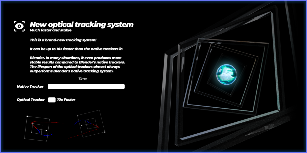
Optical Tracker Max Change: Defines how much change between frames is acceptable for optical flow trackers. A lower value causes large movements to be ignored, making the tracker more conservative. A higher value allows tracking to continue even during significant motion, which may result in inaccurate tracking or cause trackers to persist even when the original pattern has moved out of frame. (This setting only affects optical trackers.)
Optical Threshold: Defines the minimum correlation required between frames for an optical tracker to continue. A lower threshold allows trackers with weaker correlation to keep tracking, while a higher threshold makes the system more restrictive, stopping trackers sooner if the match quality drops. (This setting only affects optical trackers.)
Detect features settings
Add Trackers: When enabled, both the native track button and the optical track button will add new trackers when clicked. (This setting affects both optical and native trackers.)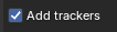
Fewest Trackers: When enabled, new trackers added using either the optical track button or the regular track button will be placed on the frame with the fewest existing trackers. (This setting affects both optical and native trackers.)
Lowest Coverage: When enabled, new trackers added using either the optical track button or the regular track button will be placed on the frame with the lowest overall tracker coverage. (This setting affects both optical and native trackers.)
Threshold, Min Distance, and Margin: These sliders control how feature detection behaves: Threshold determines how strong or well-defined a feature must be for a new tracker to be added. Min Distance sets the minimum spacing required between individual trackers to avoid overlap. Margin specifies the minimum distance from the edges of the frame where new trackers can be placed. (This setting affects both optical and native trackers.)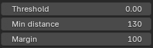
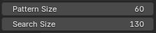
Pattern Size and Search Size:
These settings control how Blender’s native tracking algorithm searches for features between frames: Pattern Size sets the size of the square area around each tracker that defines the feature to follow. This is the pattern the algorithm tries to match in the next frame. Search Size defines the size of the area in which the algorithm looks for that pattern. A larger search area allows tracking of faster movements but may be slower or less accurate. (This setting affects only native trackers.)
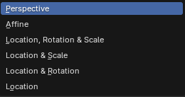
Motion model: This determines the type of motion Blender tries to estimate between frames. More complex models allow for more detailed tracking but can also be slower or more sensitive to noise (This setting affects only native trackers.):
-
Perspective:
Tracks full perspective distortion, including changes in angle, rotation, scale, and shear. Ideal for tracking planar surfaces that move in 3D space. -
Affine:
Supports rotation, scale, shear, and translation, but not full perspective distortion. Useful for moderately complex motion on flat surfaces. -
Location, Rotation & Scale:
Tracks movement, rotation, and size changes, but ignores perspective and shear. -
Location & Scale:
Tracks movement and zooming (scale), but no rotation or perspective. -
Location & Rotation:
Tracks movement and rotation, but ignores scaling and perspective. -
Location:
Only tracks the position of the pattern. This is the simplest and most stable mode, suitable when minimal movement is expected.

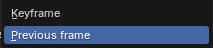
Match: This setting determines which frame Blender compares the current frame to during tracking. The choice affects how motion is estimated and can influence tracking stability. (This setting affects only native trackers.)
Previous Frame
Blender matches the tracking pattern to the immediately preceding frame. This option is more stable for most use cases, especially when tracking continuous, smooth motion. It reduces the chance of drift over time and is generally recommended.-
Keyframe
Blender compares every tracked frame to the original keyframe where the tracker was first placed. This can help prevent long-term drift over many frames but may cause tracking to fail if the motion is too fast or the object changes significantly over time.

Prepass: When enabled, Blender performs a pre-analysis of the frames to improve tracking stability and accuracy. This is especially helpful when tracking in noisy or low-contrast footage. (This setting affects only native trackers.)
Normalize: Normalizes the brightness and contrast of the tracked area between frames. This improves tracking performance in footage with lighting changes or exposure shifts. (This setting affects only native trackers.)
Optical trackers settings:
Optical pattern size: Defines the pattern size used by optical trackers. A larger value provides more stability but may result in increased drift over time. A smaller value reduces drift but can make tracking less stable. (Recommended range: 20–80. This setting only affects optical trackers.)
Optical Pyramid Levels: Specifies the number of pyramid levels used in optical tracking. Higher values allow the trackers to handle larger motion between frames, while lower values may result in jittery or unstable tracking. (Recommended: 10 or higher. This setting only affects optical trackers.)
Optical Iterations: Sets the number of iterations performed per frame during optical tracking. Higher values result in more accurate tracking but increase loading time, while lower values speed up processing at the cost of accuracy. (Recommended: 40 or more. This setting only affects optical trackers.)
Optical Minimum Accuracy: Defines the threshold for the minimum required change between successive iterations during optical tracking. Once changes fall below this value, the algorithm stops iterating, assuming it has converged. (Recommended: 0.001. This setting only affects optical trackers.)
3. Filter & solve tracks
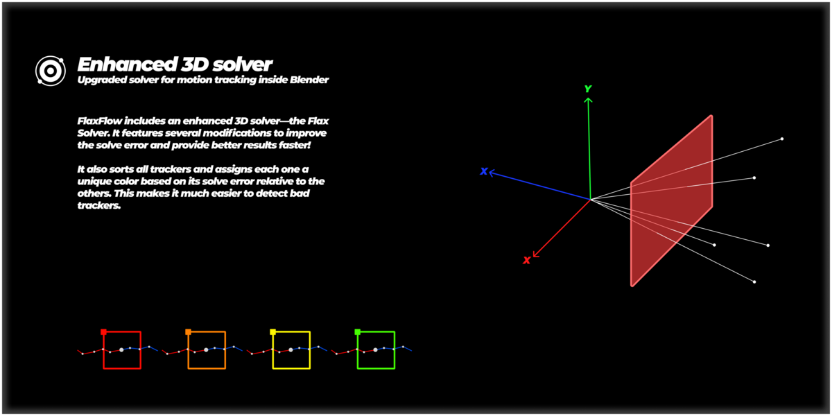
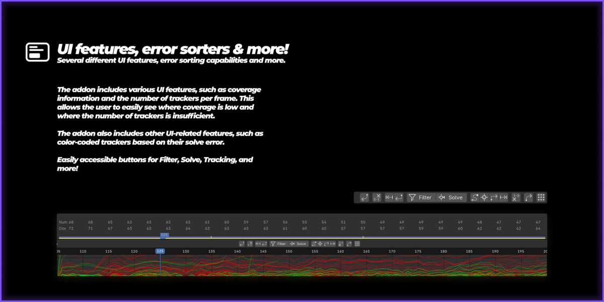
Flax Solve: Recalculates the camera solve using an enhanced solver compared to Blender’s default. The solver settings can be fine-tuned via the constraint options below this button. Once complete, each tracker is color-coded according to its reprojection error, trackers with higher error appear in red, while those with lower error appear in green. (Note: This feature is also available in the bottom center panel.)

Use Chess Pattern Calibration Values: Instructs the solver to skip estimating focal length, optical center, and lens distortion. Instead, it applies the predefined values obtained from chessboard pattern calibration and uses them directly in the solve.
Focal Length, Optical Center, and Distortion: When enabled, these options lock their respective properties during the Flax Solve process, preventing them from being recalculated automatically. For example, enabling Focal Length will use the current focal length value instead of solving for it. This is useful when working with known camera parameters, allowing for faster and more accurate results.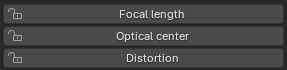
Filter:
Use Number: Allows the user to specify an exact number of trackers to remove when using the filter option, instead of filtering based on a percentage.
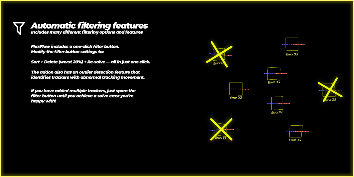
Percentage Filter Amount or Number Filter Amount: Specifies how many of the worst trackers to remove (or select, if Delete is disabled) when using the filter button. For example, if the filter amount is set to 30% and Delete is enabled, the bottom 30% of trackers, based on their solve error—will be removed during each filtering operation.

Delete: When enabled, the filter feature will delete the selected trackers instead of simply selecting them. 
Re-solve: When enabled, the filter feature automatically performs a new solve after each filtering operation. (Note: This requires Delete to be enabled in order to take effect.)
Min Number for Filter: Specifies the minimum number of active trackers required on every frame for the filter function to run. For example, if a frame has only 6 active trackers and the minimum is set higher, the filter will not execute and will instead display a warning, recommending the user to add more trackers.
Filter Trackers: Filters trackers based on the current filter settings. When clicked, it sorts all trackers by their solve error, selects or deletes the worst ones (depending on settings), and optionally re-solves using the Flax Solver. This feature is designed to be used iteratively, allowing users to gradually reduce solve error to their desired level. (Note: This feature is also available in the bottom center panel.) 

Find Track Outliers: Analyzes the motion of all trackers and calculates an outlier score for each one based on how unusually they move compared to the rest. This helps identify trackers that may be causing instability or inaccuracy in the solve. 
Select Track Outliers: Uses the outlier scores generated by the Find Track Outliers feature to select all trackers with scores worse than the specified threshold. (Note: You must first run Find Track Outliers; otherwise, no outlier scores will be available for selection.)
Chess pattern calibration:
Flax Chess Pattern Calibrator: Uses the folder path captured via the Use Current Footage button and analyzes each image in that folder to detect a checkerboard pattern, based on the specified number of rows and columns in the Chess Pattern Calibrator settings. Once activated, it estimates the camera's distortion and focal length using all detected patterns. (Note: For accurate calibration, the checkerboard must be fully visible in every image, with all rows and columns clearly shown. The pattern should also cover as much of the image area as possible without going out of frame.)
Number of Rows in Checker Pattern: Specifies the number of rows in the checkerboard pattern used for calibration. This value must match the number of rows in the actual checkerboard pattern shown in the footage.
Number of Columns in Checker Pattern:
Specifies the number of inner columns in the checkerboard pattern used for calibration. This value must match the number of columns in the actual checkerboard pattern shown in the footage.
Sensor Width (mm): Allows the user to enter the physical sensor width of their camera (in millimeters). This ensures that the calculated focal length during calibration is accurate and corresponds correctly to real-world values.
Use chess pattern calibration values: Instructs the solver to skip estimating focal length, optical center, and lens distortion. Instead, it applies the predefined values obtained from chessboard pattern calibration and uses them directly in the solve.
ST Texture Generator: Generates a standard ST texture, which can be used alongside the STMap Export feature to apply distortion or undistortion based on the current camera's principal point and distortion values. This allows for exporting an STMap that can be used in third-party software like Nuke, enabling a non-destructive undistortion workflow during rendering.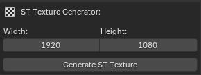
(Extra) STMap Export Node:
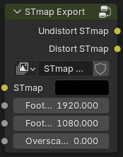
This node is available in Blender’s Compositor tab and is used to generate and export an STMap based on your footage’s distortion or undistortion settings.
How to use it:
-
Add an Image Texture Node and select the ST texture you generated using the ST Texture Generator.
-
Add the STMap Export Node, connect the Image Texture to its input.
-
Connect the Undistorted or Distorted output of the STMap Export node to the Composite and Viewer nodes, depending on whether you want to export the undistortion or distortion map.
-
Enter the Node Group: Select the STMap Export node and press Tab to enter it.
-
Inside the node, select your current footage in both the Undistorted and Distorted nodes marked in orange.
-
If the STMap doesn’t fit the view area:
-
Try increasing the Resolution Scale in the Render Properties tab (e.g., from 100% to 105%).
-
For higher resolution, increase the Overscan slider on the node itself.
-
-
To refresh the view in the Viewer node, toggle mute on and off to force an update.
-
When ready, press F12 to render the STMap.
-
In the Render Preview Window, go to Image → Save As to export the STMap to your disk.
4. Add geometry
(Note: For the geometry features to work correctly, your footage must be solved, and the solve error should ideally be below 1.0 px for reliable results.)
Automatic One-Click Geometry: When the user holds Ctrl + Shift + Right Click in the viewport within the Motion Tracking workspace, this feature attempts to estimate the 3D position of the point under the cursor. For best results, the footage should be solved with a solve error below 0.7 px. Results can be further improved by adjusting the Locator Settings explained below. (Note: If the camera has significant distortion, it is recommended to use the Manual One-Click Geometry feature instead for more accurate results.)
Locator Pattern Size: Controls the pattern size of added locators. A larger value makes the locator more stable but may struggle with accuracy near edges and corners. A smaller value may result in more variation in the 3D position but tends to perform better in tight or detailed areas.
Locator Search Size: Sets the search area used when placing locators. A higher value improves accuracy but increases the delay when right-clicking. A lower value speeds up placement but may reduce tracking precision.
Locator Track Limit: Determines how many frames are used to track the locator. A higher value increases accuracy and stability of the estimated 3D position but also increases the delay. A lower value results in faster placement but may reduce precision.
Manual One-Click Geometry:
If the scene is solved, this feature allows the user to manually estimate a 3D point by using Ctrl + Shift + Middle Click in the viewport within the Motion Tracking workspace. First, click on a point in one frame, then go to a different frame and Ctrl + Shift + Middle Click on the same point from the new camera view. The system uses the solved camera positions to triangulate the closest intersection point of the two rays cast from each click, resulting in a highly accurate 3D position estimate. (Note: The greater the distance between the camera positions in the two selected frames, the more accurate the triangulation and resulting 3D point will be.)
Jump: When enabled, each time the user clicks using the Manual One-Click Geometry feature, the timeline will automatically advance by the number of frames specified in Jump Amount. This allows for a faster and more efficient workflow by eliminating the need to manually scrub between frames when placing geometry from different camera positions.
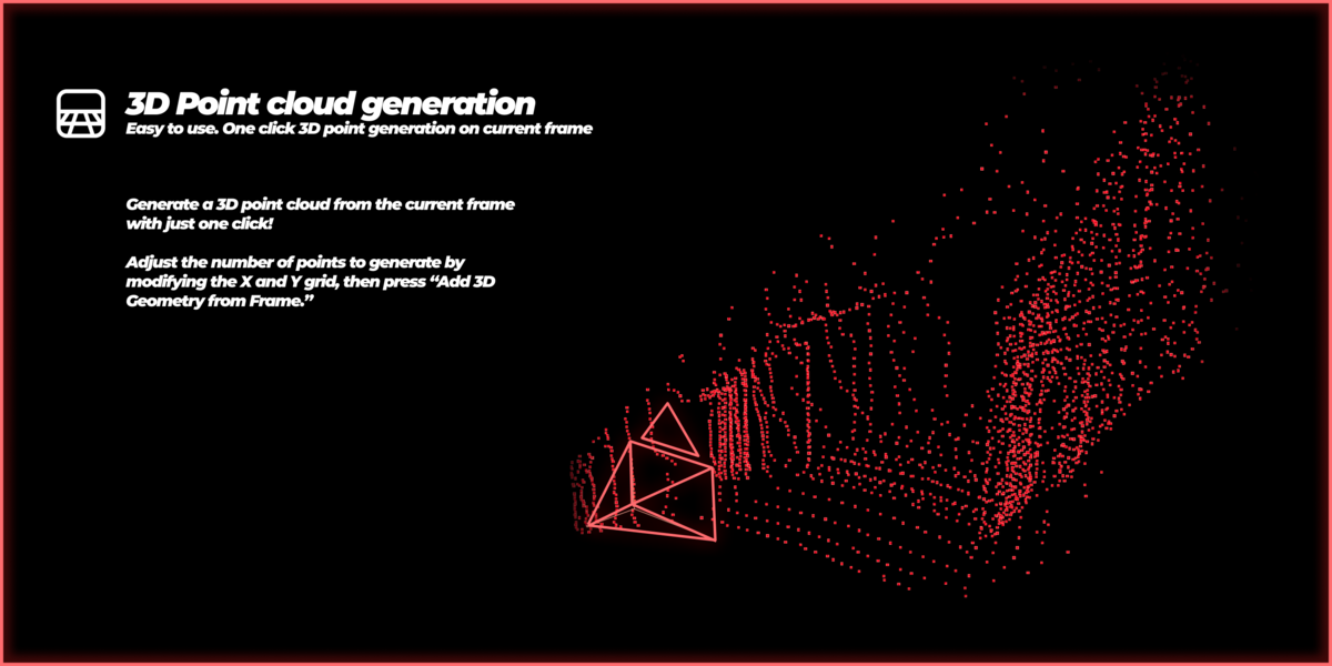
Point Cloud Geometry: Allows the user to define the X and Y size of a grid and automatically estimates a 3D point for each position within that grid. This results in a relatively high-resolution point cloud, useful for reconstructing scene geometry or visualizing spatial depth.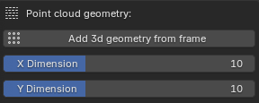
Convert to Mesh: When enabled, the generated point cloud will also be used to create a mesh. (Note: This option must be enabled before generating the point cloud in order for the mesh to be created.)
Extra
When the user removes trackers, adds trackers, performs a solve, or uses the filter function, the UI Track Element Counter is automatically updated. It displays the number of trackers present on each frame as well as the percentage of each frame that is covered by trackers, providing a quick overview of tracking density and coverage throughout the footage.

Have questions about this product?
Login to message
| Blender Extension Compatible | Yes |
| Sales | 400+ |
| Rating | 3 ratings |
| Dev Fund Contributor | |
| Published | over 1 year ago |
| Blender Version | 4.3, 4.2, 4.1, 4.0, 3.6 |
| Extension Type | Add-on |
| License | Royalty Free |
Discover more products like this
2025 FlaxFlow visual effects addon Optical trackers Geometry optical VFX tracking flaxtrax cgi Solving Motion Tracking blender for vfx Axel Olsson 2025addon One-click-geometry