Fracture Cutter
 Blender Procedural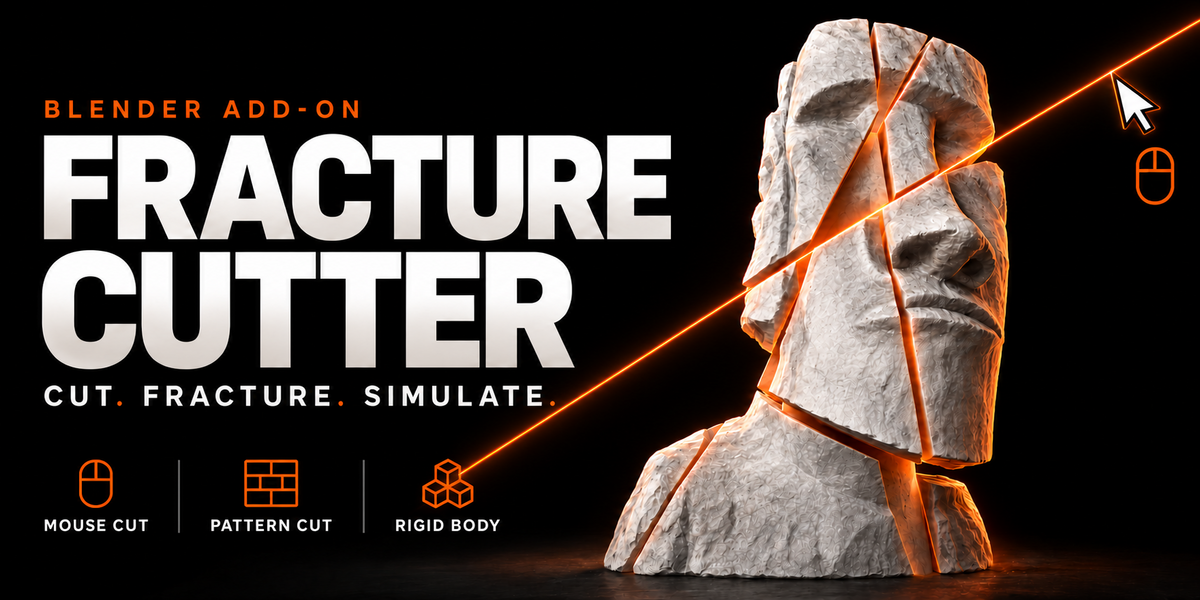
USER GUIDE
Fracture Cutter provides viewport cutting, pattern-based fracturing, fragment settings, damage tools, and rigid body setup. This guide follows the controls in the Fracture Cutter sidebar panel.
1. Installation & Opening the Panel
- Download the Fracture Cutter installation package from your purchase.
- In Blender, open Edit > Preferences > Add-ons.
- Open the menu in the upper-right corner and choose Install from Disk. Select the installable Fracture Cutter package. If the download contains a separate installation ZIP inside an outer archive, select the installation ZIP.
- Find Fracture Cutter in the Add-ons list and enable it if it is not already enabled.
- Return to the 3D Viewport, select your mesh, and use Object Mode.
- Move the pointer over the viewport and press N to open the sidebar. Open the Fracture tab and expand the Fracture Cutter panel.
Installation menu placement can vary by Blender version. Use a version listed as supported on the product page.
2. Quick Start
- Select the mesh you want to fracture.
- Choose Clean or Rough under Cut Style.
- Set the options in Result. Enable Keep Original (Hidden) if you want to retain the source object.
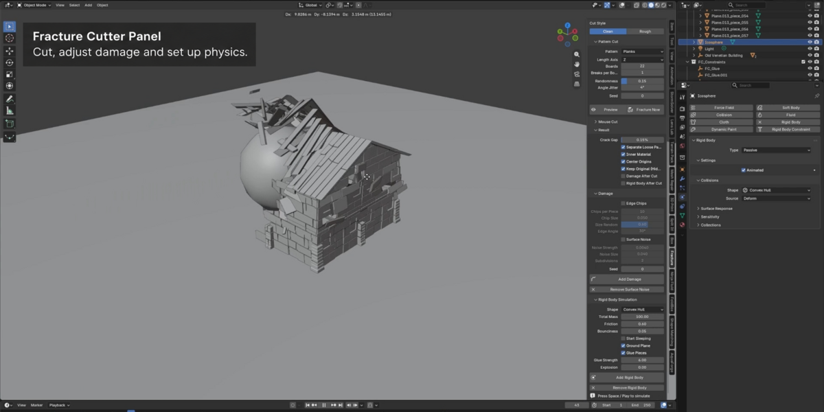
- For a pattern, open Pattern Cut, choose the pattern, adjust its settings, and click Preview. Click Apply when satisfied. Use Fracture Now to apply the pattern directly.
- For custom cuts, click Mouse Cut, draw across the object, and press Enter to finish.
- Optionally add edge chips or surface noise with Add Damage.
- Select the fragments you want to simulate, configure Rigid Body Simulation, and click Add Rigid Body.
- Start playback from the beginning of the simulation to inspect the result.
3. Cut Style
- Clean: Choose this style for a cleaner cut appearance.
- Rough: Choose this style for a rougher cut appearance.
During Mouse Cut, press R to switch styles. Edge Chips and Surface Noise are separate controls in the Damage section.
4. Mouse Cut
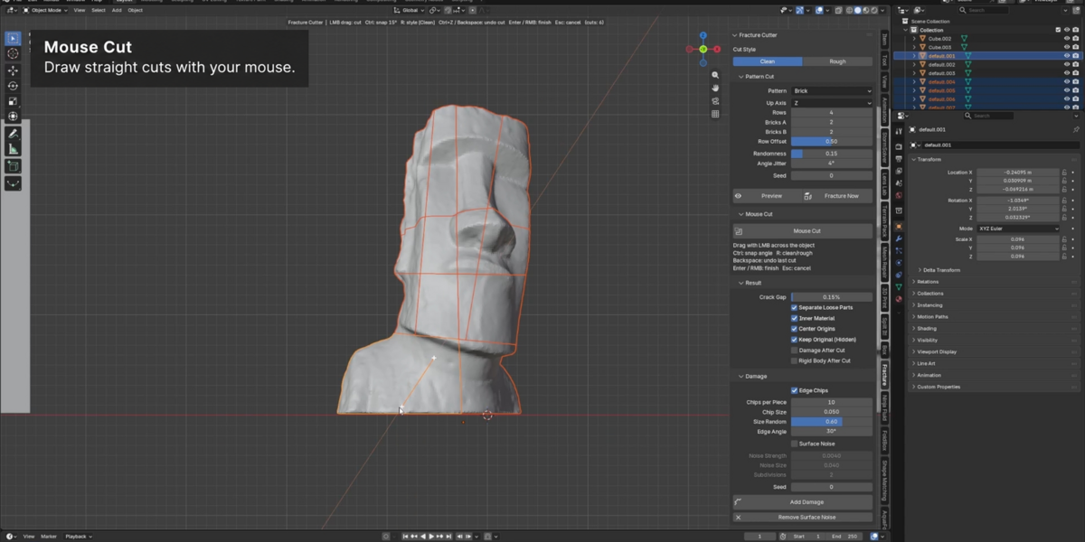
Use Mouse Cut to place cuts manually across the object in the viewport.
- Select the target mesh and position the view so you can see the area you want to cut.
- Expand Mouse Cut and click the Mouse Cut button.
- Click and drag with the left mouse button across the object to draw a cut.
- Repeat to add more cuts. Use the shortcuts below while the tool is active.
- Press Enter or the right mouse button to finish, or Esc to cancel.
| Input | Action while Mouse Cut is active |
|---|---|
| Left mouse button + drag | Draw a cut across the object. |
| Ctrl while drawing | Snap the cut angle in 15° increments. |
| R | Switch between Clean and Rough styles. |
| Backspace or Ctrl + Z | Undo a cut in the active cutting session. |
| Enter or right mouse button | Finish the cutting session. |
| Esc | Cancel the cutting session. |
Tip: A front, side, or top orthographic view can make it easier to position cuts consistently.
5. Pattern Cut
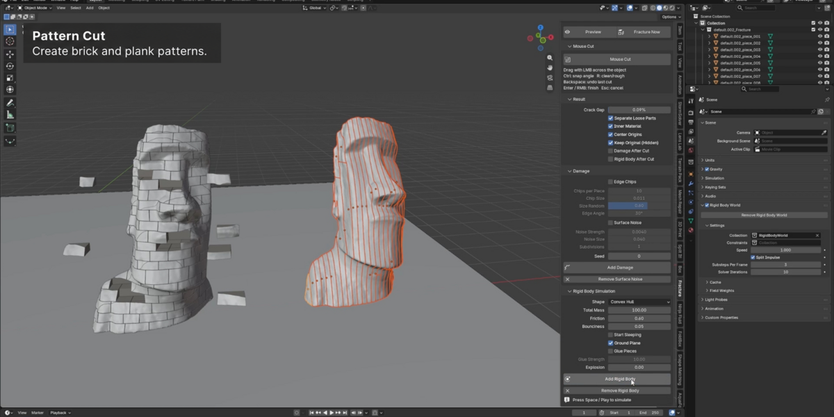
Pattern Cut generates a structured breakup. The displayed settings change with the selected pattern.
Brick
- Up Axis: Choose the axis used for the vertical direction of the brick layout.
- Rows: Set the number of brick rows.
- Bricks A / Bricks B: Set the two brick-count controls used by the pattern. Inspect the preview to see their effect on your model.
- Row Offset: Adjust the stagger between rows.
Planks
- Length Axis: Choose the direction of the planks.
- Boards: Set the board count for the pattern.
- Breaks per Board: Control the breaks along each board.
Shared Pattern Settings
- Randomness: Adjust variation in the pattern layout. Start low for a more regular arrangement.
- Angle Jitter: Adjust angular variation in the cuts.
- Seed: Change the random seed to try a different arrangement.
- Preview: Inspect the breakup before applying it.
- Fracture Now: Apply the current pattern directly.
Working with the Preview
After clicking Preview, the panel displays a piece count and additional preview controls.
- Apply: Accept the preview and create the fractured result.
- Cancel: Discard the preview.
- Explode View: Spread the preview pieces apart for inspection. Return it to zero to inspect the assembled shape. This is a preview display control; simulation has a separate Explosion setting.
- Fast Preview: Use the fast preview option while exploring the breakup.
- Color Pieces: Display pieces in different colors to make fragment boundaries easier to see.
- Live Update: Update the preview as you change settings. If interaction becomes slow, disable it and use the refresh button after making adjustments.
Tip: Inspect the actual piece count. Pattern counts do not necessarily equal the final number of fragments on an irregular mesh.
6. Result Settings
Configure these options before creating the fractured result.
- Crack Gap: Adjust the visible gap between fragments. Use a small value to keep the overall shape close to the original.
- Separate Loose Parts: Separate disconnected parts into individual objects. Enable this when you want to work with individual fragments.
- Inner Material: Enable the inner-material option for newly exposed cut surfaces.
- Center Origins: Center the origins of the resulting pieces for easier object handling.
- Keep Original (Hidden): Retain a hidden copy of the original object.
- Damage After Cut: Apply the configured damage as part of the cutting workflow.
- Rigid Body After Cut: Add rigid body setup as part of the cutting workflow.
When using the automatic options, configure Damage and Rigid Body Simulation before cutting. For more control over each stage, leave them disabled and use Add Damage and Add Rigid Body afterward.
7. Damage
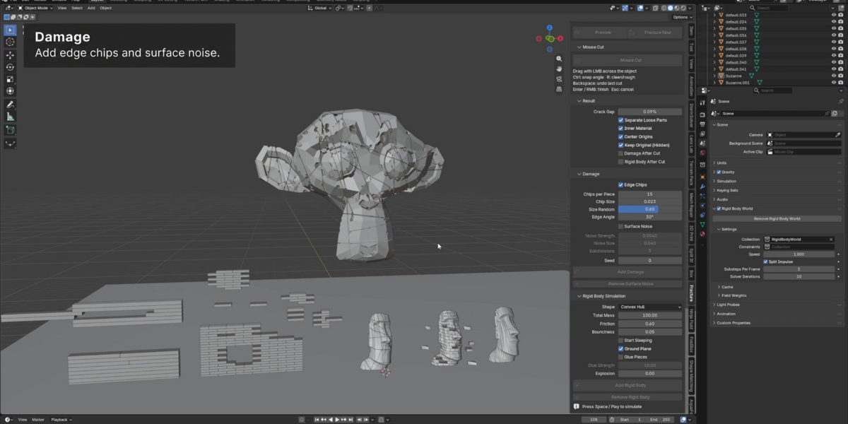
Select the pieces you want to damage. Enable Edge Chips, Surface Noise, or both, adjust their settings, and click Add Damage.
Edge Chips
- Edge Chips: Enable the edge-chipping effect.
- Chips per Piece: Set the chip-count setting for each piece.
- Chip Size: Set the size of the chips.
- Size Random: Adjust variation in chip size.
- Edge Angle: Adjust the edge-angle setting used by the chipping effect.
Surface Noise
- Surface Noise: Enable the surface-noise effect.
- Noise Strength: Control the amount of surface deformation.
- Noise Size: Adjust the scale of the noise detail.
- Subdivisions: Set the subdivision level used for surface detail. Higher values can increase geometry and processing time.
- Seed: Change the random seed for the damage variation.
- Add Damage: Apply the enabled damage effects.
- Remove Surface Noise: Remove the surface-noise effect. This button is specifically for surface noise; do not use it as a general undo for edge chips.
Tip: Start with small chip sizes and low noise strength. The appropriate values depend on the size and detail of your object.
8. Rigid Body Simulation
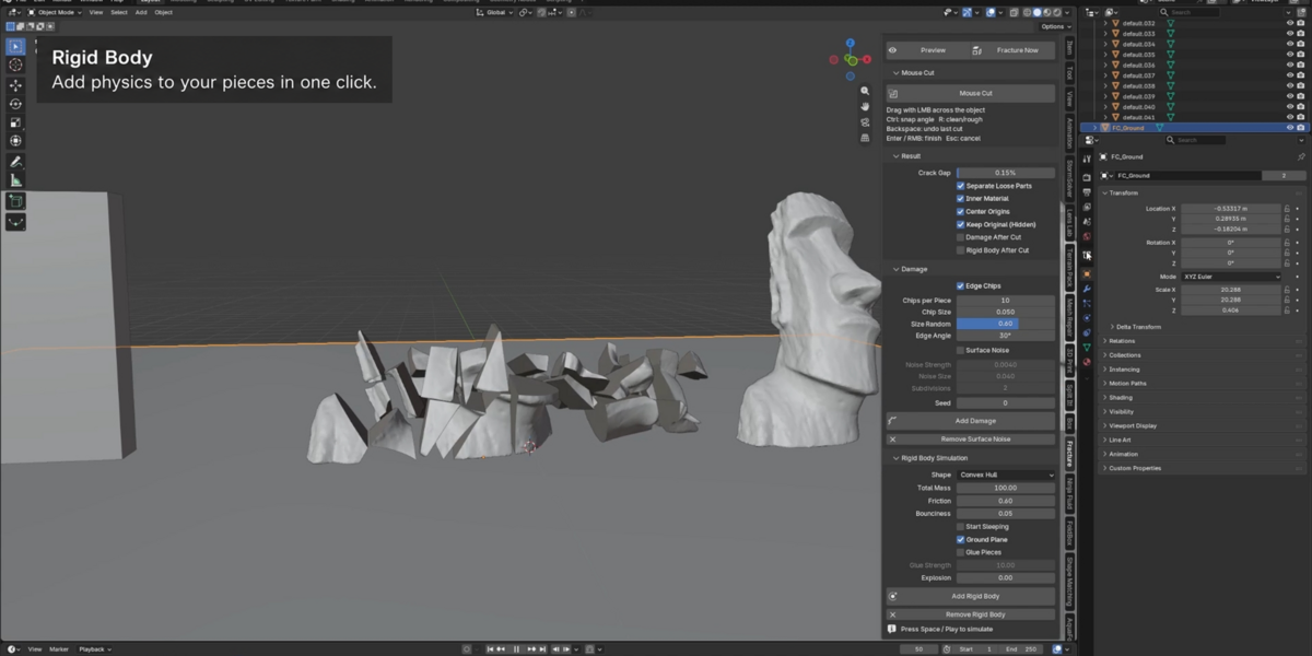
Select the fractured pieces you want to simulate and open Rigid Body Simulation.
- Shape: Choose the collision shape. Convex Hull is the option shown in the demonstration.
- Total Mass: Set the total-mass setting for the rigid body setup.
- Friction: Adjust resistance to sliding on contact.
- Bounciness: Adjust how much pieces rebound on contact.
- Start Sleeping: Start bodies in a sleeping state. This can be useful when pieces should remain still until the simulation activates them.
- Ground Plane: Enable the ground-plane option for the simulation setup.
- Glue Pieces: Enable glue connections between pieces.
- Glue Strength: Adjust the strength setting of the glue connections. Test it with your scene's scale and impacts.
- Explosion: Adjust the explosion setting for the rigid body setup. Start at zero when you want to evaluate the scene without an explosion effect.
- Add Rigid Body: Create the rigid body setup for the selected pieces.
- Remove Rigid Body: Remove the rigid body setup from the selected pieces.
Click Add Rigid Body, return to the start of the simulation, and press Space or use the timeline Play button. Use the Play button if your Blender keymap assigns Space to another action.
Collision tip: Convex Hull approximates each object with a convex shape, so concave openings may not behave like the visible mesh. Inspect collision settings if contact looks incorrect.
9. Example Workflows
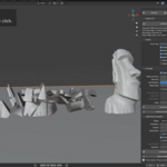
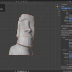
A. Manually Fracture a Statue
- Select the statue mesh and use a clear front view.
- Choose Clean or Rough and enable Keep Original (Hidden).
- Click Mouse Cut and draw several cuts across the shape.
- Press Enter to finish.
- Select the resulting pieces and add Edge Chips if needed.
- Enable Ground Plane and click Add Rigid Body, then play the simulation.
B. Create a Brick Breakup
- Select the target mesh and choose Brick.
- As a starting point, try Up Axis: Z, Rows: 4, Bricks A: 2, Bricks B: 2, Row Offset: 0.50, Randomness: 0.15, Angle Jitter: 4°, Seed: 0 .
- Click Preview and inspect the layout. Increase counts if the pieces are too large for your model.
- Adjust Crack Gap and Result options, then click Apply.
- Optionally add damage and rigid bodies. Enable Glue Pieces if your simulation needs connected fragments.
C. Create Broken Planks
- Select the target mesh and choose Planks.
- Choose the Length Axis that matches your intended plank direction.
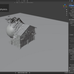
- The demonstrated roof preview uses Length Axis: Z, Boards: 22, Breaks per Board: 3, Randomness: 0, Angle Jitter: 0°, Seed: 0 . Use these as an example, then adjust them for your model.
- Click Preview, enable Color Pieces, and inspect the fragments with Explode View.
- Click Apply and set up rigid bodies if you want to animate the breakup.
These example values come from the demonstrated panel settings. They are starting points, not universal defaults or guaranteed results for every mesh.
10. Troubleshooting & Performance
- The panel is missing: Check that Fracture Cutter is enabled, the pointer is over the 3D Viewport, and the sidebar is open with N. Look for the Fracture tab.
- A button is unavailable: Finish or cancel any active cutting or preview session. Check Object Mode and the current mesh selection. Some controls depend on the current operation.
- The preview is slow: Reduce pattern counts, enable Fast Preview, or disable Live Update while adjusting settings.
- The pattern faces the wrong direction: Check Up Axis for Brick or Length Axis for Planks.
- The cracks are too wide: Reduce Crack Gap.
- The damage is too strong: Reduce Chip Size or Noise Strength and test on a copy before applying more damage.
- Fragments do not move: Check that rigid bodies have been added and playback starts from the beginning. Review Start Sleeping and Glue Pieces settings.
- Collision contact looks wrong: Review collision shape, mesh scale, initial overlaps, and Blender's rigid body settings.
- The simulation is slow: Reduce fragment count and damage subdivisions. Test the fracture first, then add detailed damage.
- You need the original mesh: If Keep Original (Hidden) was enabled, locate and unhide the retained source object in the Outliner.
Video Demonstration & Support
Watch the Fracture Cutter demonstration on YouTube ↗
For support, contact the creator through Superhive. Include your Blender version, Fracture Cutter version, the steps that caused the issue, and a screenshot of the panel or any error message.
Blender references: add-on installation and rigid body collisions .
Have questions about this product?
Login to message
| Blender Extension Compatible | Yes |
| Dev Fund Contributor | |
| Published | about 8 hours ago |
| Blender Version | 5.0 - 5.2 |
| Extension Type | Add-on |
| Render Engine Used | Cycles, Eevee |
| License | GPL |
Discover more products like this
pattern cut destruction Damage fracture brick Mesh Cutting debris rigid body planks mouse cut VFX simulation