Print Forge
 Creative Collections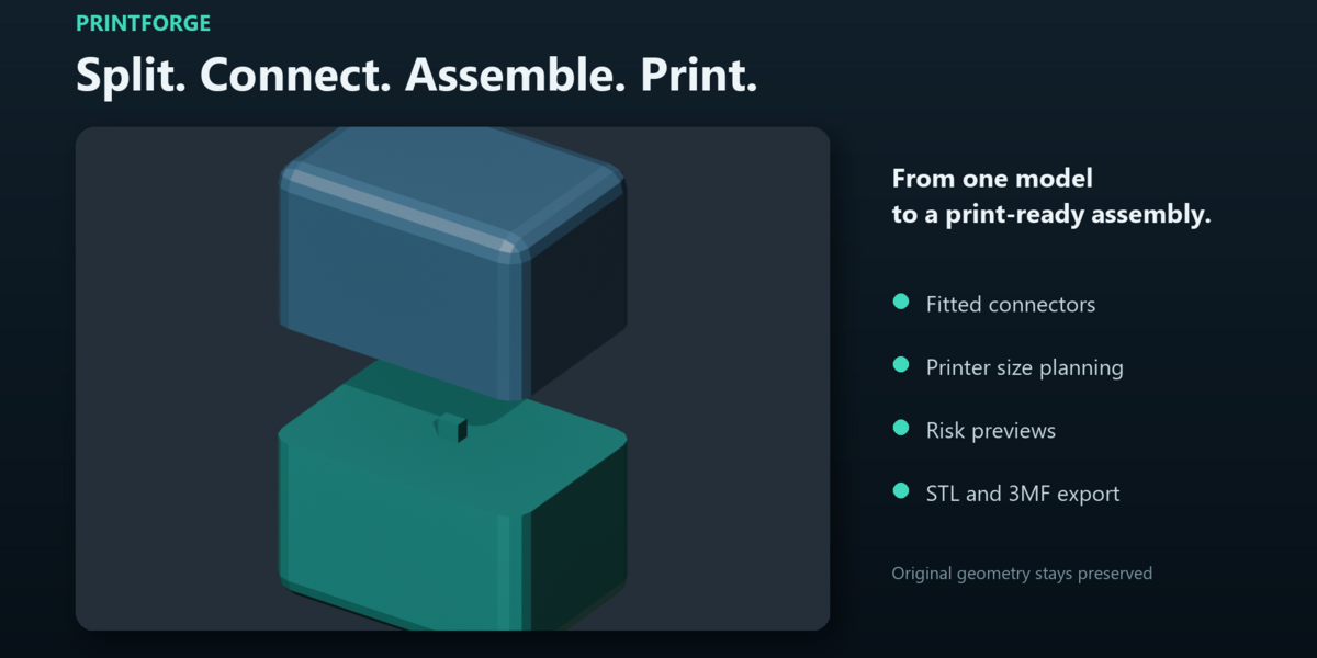
PrintForge User Guide
Version 1.0
Overview
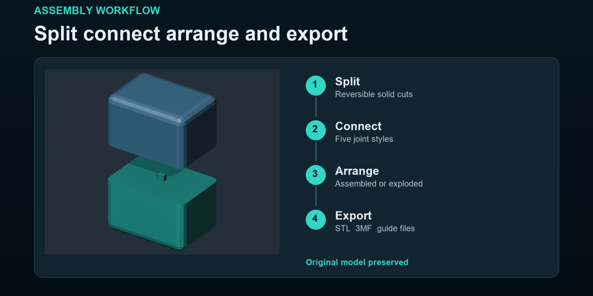
PrintForge prepares solid Blender models for printing. It checks model dimensions, identifies common print risks, creates reversible cuts, adds fitted connectors and exports organized assembly packages.
PrintForge preserves the original model while creating numbered production parts. It runs locally and does not require an account, cloud connection or additional software.
Requirements
Blender 4.2 or newer
A closed solid mesh for cutting and exporting
A slicer for final orientation, supports and printer settings
Installation
Open Blender.
Open Edit and select Preferences.
Open Add ons and choose Install from Disk.
Select PrintForge 1.0.0.zip without unpacking it.
Enable PrintForge.
Return to the 3D View.
Press N and select the PrintForge tab.
Using the demonstration file
Open PrintForge Demo.blend to explore a prepared assembly.
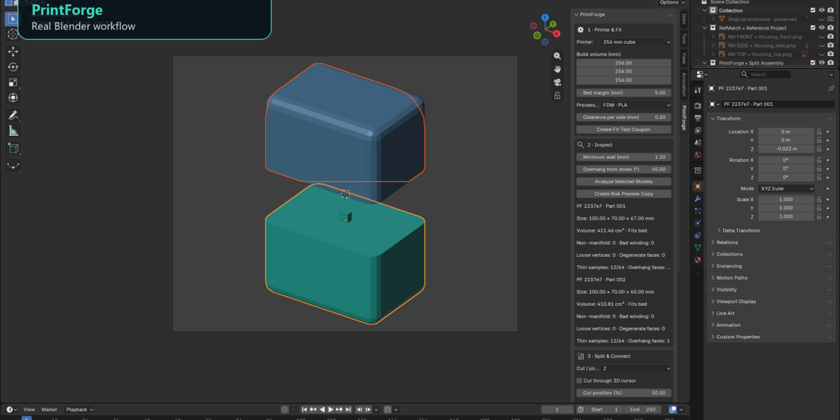
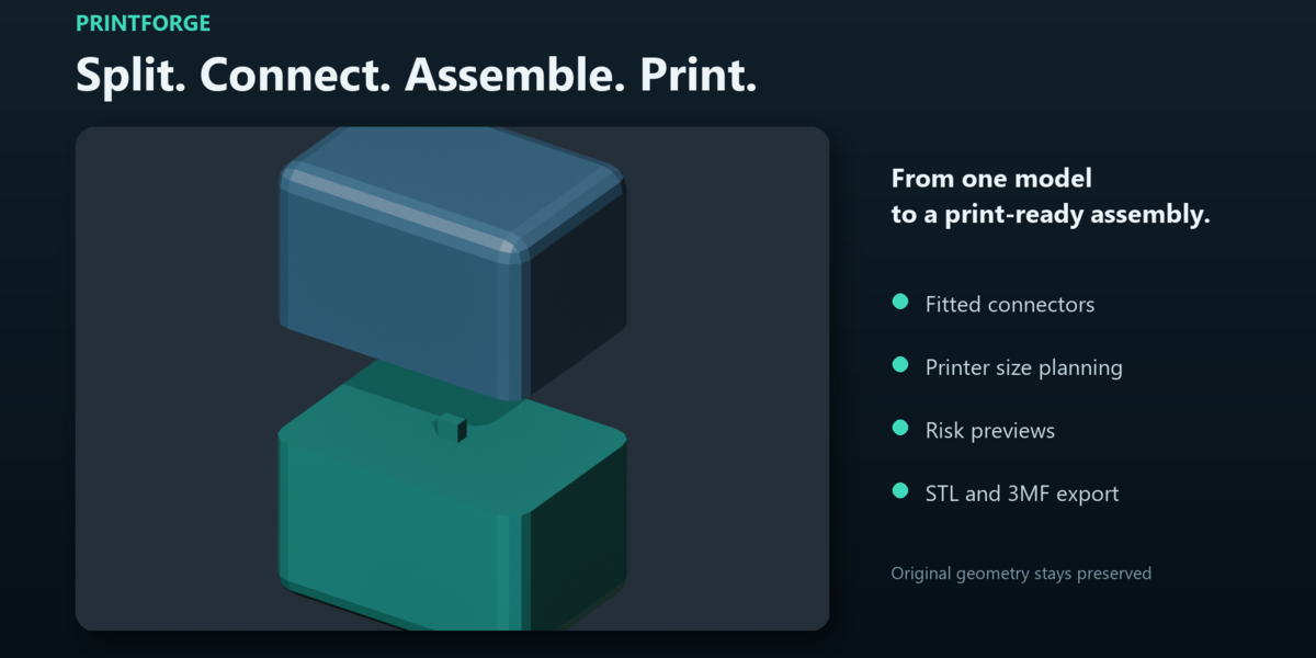
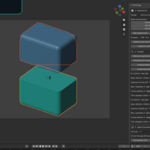
The demonstration contains two numbered enclosure parts shown in an exploded view. The lower part includes a keyed pin and the upper part includes its matching clearance socket.
Select Assembled to restore the parts to their original positions. The original enclosure remains preserved and hidden in the Outliner.
Printer and fit settings
Choose a printer preset or enter the usable X, Y and Z build dimensions in millimeters.
Printer presets only provide dimensions. PrintForge does not connect to or control the printer.
Set the bed margin to reserve space around the edges of the build plate. PrintForge subtracts two margins from every axis when calculating the usable volume.
Choose a printing process and material as a starting point for connector clearance. You can also enter your own calibrated clearance.
Clearance is applied on every side of a connector. A round pin with a diameter of 6 millimeters and a clearance of 0.2 millimeters creates a socket diameter of 6.4 millimeters.
Fit test coupon
Select Create Fit Test Coupon to generate two small test parts.
Print the coupon using the same material, layer height, orientation and printer settings planned for the final assembly.
Test the physical fit and adjust the clearance before preparing a large print.
Model inspection
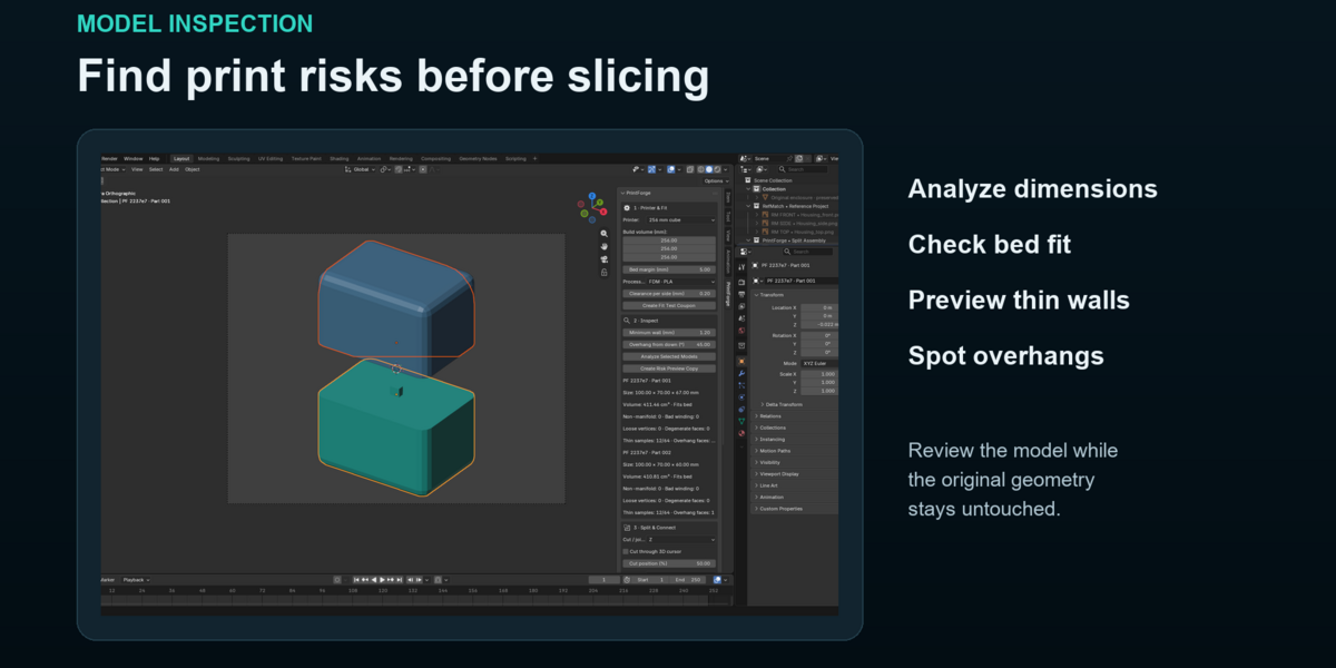
Select one or more mesh objects in Object Mode and choose Analyze Selected Models.
The report includes the following information.
Model dimensions
Build volume fit
Mesh volume
Open or non manifold edges
Inconsistent face direction
Loose vertices
Degenerate faces
Sampled thin walls
Overhangs relative to world Z
All dimensional settings respect the Blender scene unit scale. Analyze imported models before splitting or exporting to confirm that their physical dimensions are correct.
Risk preview
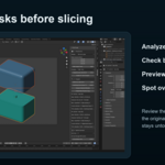
Select Create Risk Preview Copy to generate a separate colored inspection model.
Green represents the base material.
Orange represents detected overhangs.
Red represents sampled thin wall areas.
The original geometry remains unchanged.
Thin wall inspection samples up to 2000 face centers. Small features and internal cavities can be missed. The inspection is a preparation aid and should not be treated as structural certification or resin drainage analysis.
Splitting a model
Select one closed solid mesh in Object Mode.
Choose the world axis for the cut.
Set the cut position as a percentage or enable Cut through 3D cursor.
Choose a connector type.
Set the connector size and total depth.
Enable Add centered joint to cut if a connector should be created automatically.
Select Split Model.
PrintForge preserves and hides the original source model. The new parts are selected and numbered.
Undo restores the previous state.
If the connector cannot fit safely inside both parts, PrintForge cancels the complete operation and restores the original model. Reduce the connector size, move the cut or create the split without a connector.
Connector types
Integrated round pin
Creates a round male pin on one part and a matching clearance socket on the other part.
Keyed rectangular pin
Creates a rectangular connector that resists rotation during assembly.
Loose pin sockets
Creates two blind sockets and a separate printable pin.
Magnet pockets
Creates two cylindrical pockets for magnets supplied by the user.
Insert pockets
Creates two cylindrical pockets sized for the selected hardware.
PrintForge does not generate threads or manufacturer specific insert geometry. Measure the actual hardware before creating pockets.
Automatic build volume splitting
Select Auto Split to Build Volume to divide a large model into an axis aligned grid of closed printable parts.
Every generated part is sized according to the current usable build volume.
Automatic plans are limited to 128 cells.
The tool places seams according to model size. It does not automatically identify hidden surfaces, ideal artistic seam locations or the best printing orientation.
Review every cut before adding connectors.
Adding a manual joint
Select Assembled to restore the saved assembly positions.
Select two current adjacent parts from the same assembly.
Place the 3D cursor on their shared flat seam.
Choose the world axis perpendicular to the seam.
Select Join Two Parts at Cursor.
Previous part revisions are preserved and hidden. Select only the latest revisions when exporting.
Assembly tools
Assembled
Restores every selected part to its saved assembly position.
Exploded
Moves parts away from the assembly center using the selected distance.
One Part per Plate
Places every selected part at Z zero in a separate plate position.
This tool does not pack multiple parts onto one bed and does not calculate the best printing orientation.
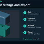
Exporting an assembly package
Save the Blender project.
Select every current assembly part that should be exported.
Choose an export folder.
Select Export Assembly Package.
PrintForge creates a new dated folder for every export.
The package contains the following files.
Individual STL files
Each part is exported in millimeters and moved to its own plate origin.
Assembly.3mf
Contains separately named assembly components in their assembled positions.
Assembly Guide.html
Contains printable part information, dimensions, filenames and recorded connections.
parts.svg
Provides a numbered visual index of the assembly parts.
assembly.json
Contains dimensions, assembly transforms, connector records and unit information for future processing.
Export protection
PrintForge rejects open meshes, duplicate revisions, mixed assemblies and parts that exceed the usable build volume.
A failed export removes its temporary files and does not overwrite earlier packages.
Save the Blender project before using a relative export directory.
Troubleshooting
The PrintForge tab is missing
Hover over the 3D View, press N and select PrintForge. Confirm that the add on is enabled in Blender Preferences.
Model dimensions are incorrect
Check the scene unit scale and run Analyze Selected Models before continuing.
The model does not fit the printer
Check the bed margin, model orientation and usable build dimensions. Use automatic splitting when necessary.
The split is cancelled
Reduce the connector size, move the cut or create the split without a connector.
A manual joint fails
Select two current adjacent parts from the same assembly. Restore their assembled positions and place the 3D cursor on the shared flat seam.
Export is rejected
Check for open meshes, duplicate revisions, mixed assemblies or parts that exceed the usable build volume.
Connectors are too tight
Print a fit test coupon and increase the per side clearance.
Connectors are too loose
Print a fit test coupon and decrease the per side clearance.
Version 1.0 features
Solid model cutting
Five connector and pocket types
Material clearance starting points
Printable fit test coupons
Printer build volume planning
Automatic size based splitting
Model risk previews
Numbered assembly parts
Assembled and exploded layouts
STL and 3MF export
Printable assembly documentation
Version 1.0 does not include automatic seam optimization, automatic support planning, automatic print orientation, dovetail joints, puzzle joints, engraved labels, generated threads, trapped resin inspection or editable procedural cut history.
Always review the final geometry, orientation and supports in your slicer before printing.
Have questions about this product?
Login to message
| Published | about 23 hours ago |
| Blender Version | 4.2 - 5.2 |
| Extension Type | N/A |
| Render Engine Used | Cycles, Eevee, Vray |
| License | GPL |

Discover more products like this
3dprint seperates 3Dprinter 3dprintableart pieces 3d print joints 3dprintable 3dprintedproducts. design 3Dmodel