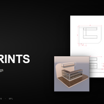
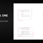
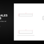
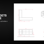
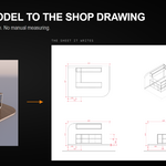
Stand Blueprints - Technical Drawings From Any Mesh
 Loops3D


Install
- Download
StandBlueprints_v1.0.0.zip. - In Blender: Edit › Preferences › Add-ons › Install from Disk and pick the ZIP.
- Enable Stand Blueprints - SVG technical drawings.
Where it lives
3D View › Sidebar (N) › Blueprints
First run
- Set Output folder.
//BLUEPRINTS/writes next to your .blend file. - Select the parts you want and press Sheet from Selection, or press Full Package to document the whole visible scene at once.
- Press Open Folder to see the result.
Naming a part
Add a custom object property named blueprint_name in the Object properties. Its value becomes the title printed on that sheet. Without it, the object name is used and cleaned up.
Sheet size
Width px and Height px set the SVG canvas. The default 1600 × 1236 is a landscape sheet. The output is vector, so these numbers only set the drawing frame — printing at any size stays sharp.
Units
Dimensions are written with two decimals and no unit suffix, the way shop drawings are usually annotated. Model in meters for the numbers to read as meters.
Option guide
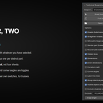
- Disable Subdivision — draws the base mesh without applying the modifier. On by default.
- Straighten rotated parts — draws a part on its own plane, so a rotated piece reports its true size. On by default.
- Silhouette (logos and cutouts) — traces the outline through the UVs. Use it on logo panels and cut-out shapes.
- Slender part (tower, profile) — lays a long piece down and spreads it in bands across the page.
- Round tube outline — outlines curved parts per view. Required for trusses and anything built from cylinders.
- Hidden lines — dashed lines for geometry behind the front face.
- Dimensions / Inner dimensions — overall sizes and internal levels.
- Curvature radii / Corner angles — off by default; turn them on when a piece needs them.
- Label the views — prints TOP / FRONT / SIDE. Off by default, because shop blueprints usually omit them.
- Group identical parts — identical parts share one sheet marked xN identical.
- Visible objects only / Include disabled collections / Exclude — control what enters a Full Package.
- Edge angle — the minimum angle between two faces for that edge to be drawn. Raise it for a cleaner drawing, lower it to catch soft creases.
Troubleshooting
- A truss draws as a row of dots — turn on Round tube outline. Lowering the edge angle will not fix it, it will only add noise.
- A logo panel draws as a blob — turn on Silhouette.
- A long part comes out tiny — turn on Slender part.
- Nothing is drawn — the selection has no mesh objects, or every candidate is hidden and Visible objects only is on.
Support
Questions and bug reports through the Superhive messaging on this product page.
Have questions about this product?
Login to message
| Published | about 2 months ago |
| Blender Version | 4.2 - 5.2 |
| Extension Type | N/A |
| Render Engine Used | Cycles, Eevee |
| License | GPL |
Discover more products like this
Technical drawing measurement millwork documentation Production exhibition stand set-design blueprint furniture dimensions SVG architecture