Wk_mechanics - Mechanical Linkage, CAM Designer & Automata
 Wolfram Kampffmeyer



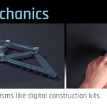
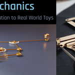
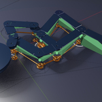
Blender Addon wk_mechanics
Installation:
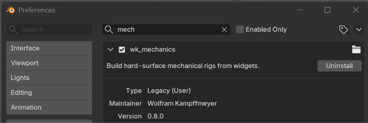
• In Blender go to Edit > Preferences > Add-ons
• Click Install, then choose the wk_mechanics*.zip file
• Enable wk_mechanics in the list
• Access it from the Sidebar (N) > wk_mechanics
Overview:
wk_mechanics is a Blender add-on for designing, testing and fabricating real mechanical linkages, automata and CAM-driven machines.
Instead of manually building constraints, rigs and fabrication drawings, you assemble mechanisms from a collection of mechanical widgets. These widgets can be combined into working linkage systems, drawing machines, walkers, automata, sliders, levers and custom kinetic designs.
Once a mechanism is created, wk_mechanics can automatically generate an animation rig, allowing you to test motion, adjust proportions and refine the design before fabrication.
A unique feature of wk_mechanics is its CAM workflow. Complex motions can be recorded directly from simulated mechanisms and converted into physical CAM profiles. This makes it possible to create sophisticated drawing machines, automata and motion-transfer systems that would be difficult to design manually.
After testing, the same mechanism can be converted into fabrication-ready blueprint parts. These parts can be edited, renamed, duplicated or customized before being flattened automatically for manufacturing. Blueprint parts include drilling holes for pivots and joints and can be exported directly as SVG files for laser cutting, CNC machining or other digital fabrication workflows.
The entire workflow takes place inside Blender:
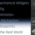
Design → Test → Simulate → Generate CAMs → Create Blueprints → Export SVG → Build in the Real World
Whether you are creating kinetic sculptures, educational mechanisms, drawing machines, automata, laser-cut toys or experimental engineering projects, wk_mechanics provides a complete pipeline from concept to physical object.
Walk-Through of some of the Building-Process:
How wk_mechanics Works:
Main Interface
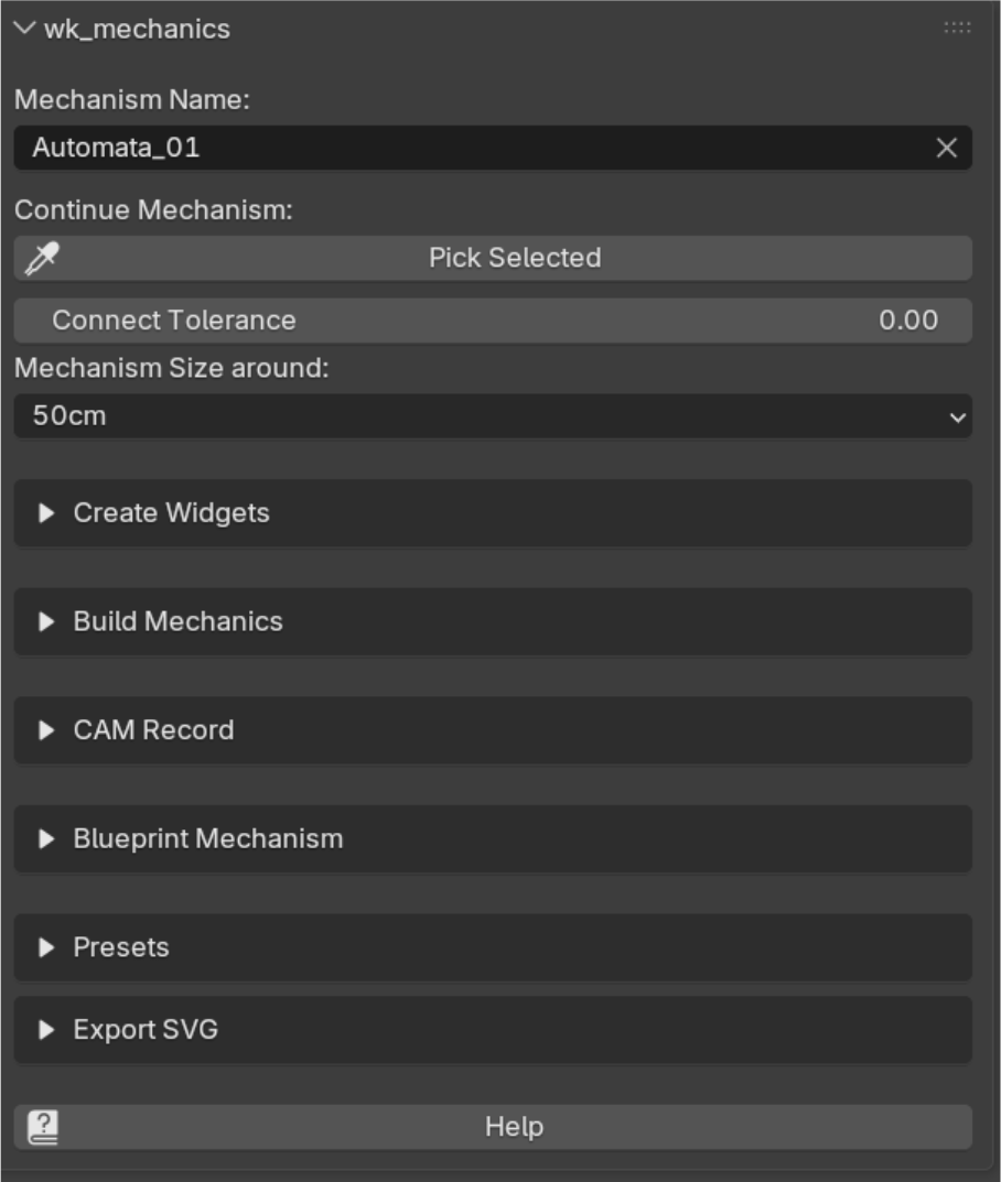
The main panel is divided into several modules that guide you through the complete workflow of designing, testing and manufacturing mechanical linkages.
Mechanism Name
Defines the name of the current mechanism. All widgets, rigs and generated objects belonging to this mechanism will be organized under this name.
Continue Mechanism / Pick Selected
wk_mechanics can manage multiple mechanisms in the same Blender scene.
Select any widget that belongs to an existing mechanism and press Pick Selected. The mechanism name is automatically loaded, allowing newly created widgets to be added to the correct mechanism and collection.
Connect Tolerance
Controls how close widget connection points must be in order to connect automatically.
A value of 0.00 requires exact alignment. Increasing the tolerance can be useful when importing or adjusting mechanisms where connection points are slightly offset.
Mechanism Size Around
Defines the approximate size of the mechanism to be created. This value is used when generating new widgets and presets, providing a suitable default scale for the mechanism.
Module Overview
Create Widgets
Contains all building blocks used to construct mechanisms.
Here you can create ChainStarts, Connectors, Sliders, Seesaws, PivotAnchors, CAMs, Rods, PenJoints and other mechanical elements. These widgets form the foundation of every mechanism.
Build Mechanics
Converts widget layouts into functional rigs and provides tools for testing, duplicating and modifying mechanisms.
This module is typically used after the basic mechanism has been assembled.
CAM Record
Generates CAM profiles from mechanism motion.
Complex movements can be recorded over time and converted into physical CAM shapes that can later drive followers in real-world mechanical assemblies.
Blueprint Mechanism
Creates fabrication-ready blueprint parts from the mechanism.
Generated parts can be edited, renamed or customized before being flattened into manufacturing layouts suitable for laser cutting, CNC machining or other fabrication methods.
Presets
Provides a collection of example mechanisms that demonstrate different principles and workflows.
New users are encouraged to start here. The presets are an excellent way to learn how mechanisms are constructed and how the various widgets interact.
Export SVG
Exports blueprint parts as SVG files for fabrication.
The generated SVG files can be imported into laser cutting, CNC or vector design software.
Help
Opens the pdf documentation and provides all informations about this addon.
Recommended for new users:
Start with the Presets. Explore the included examples, observe how the widgets are connected, and then begin modifying or creating your own mechanisms.
Please skip to the Presets Section „Start Here: Explore the Presets“!
General Workflow Tips
These tips can save a lot of time when building mechanisms and help avoid common beginner mistakes.
Use the 3D Cursor for Precise Placement
The easiest way to connect widgets is by placing them directly onto existing connection points.
Recommended Workflow
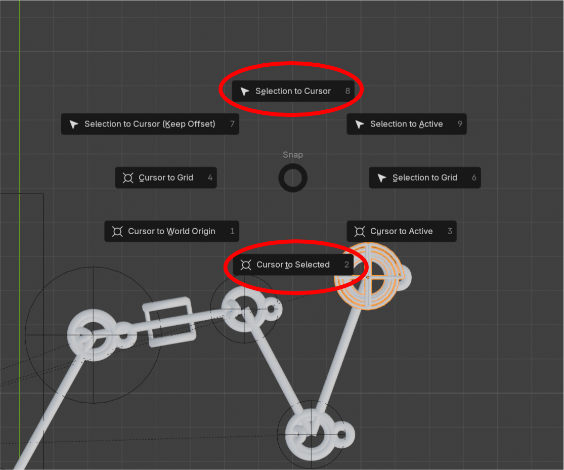
• Select the connection point you want to continue from.
• Press Shift+S → Cursor to Selected.
• Create the next widget.
• Press Shift+S → Selection to Cursor.
This places the new widget exactly on the desired connection point and avoids manual positioning.
Work in Orthographic Top View
When building mechanisms, it is highly recommended to work in Orthographic Top View (Numpad 7).
Benefits:
• Easier alignment of widgets
• Better visibility of linkage relationships
• Reduced risk of creating unintended offsets or 3D cursor rotations
Most mechanism design can be performed entirely from the top view.
Add Frequently Used Commands to Quick Favorites
Some commands are used repeatedly during mechanism design.
Blender's Quick Favorites menu (Q) provides fast access to these tools.
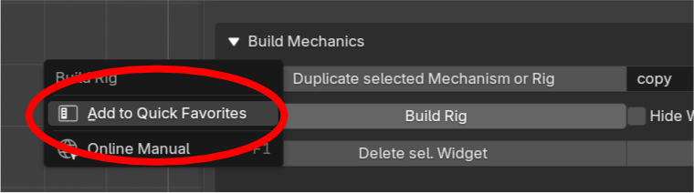
To add a command:
• Right-click the button.
• Select Add to Quick Favorites.
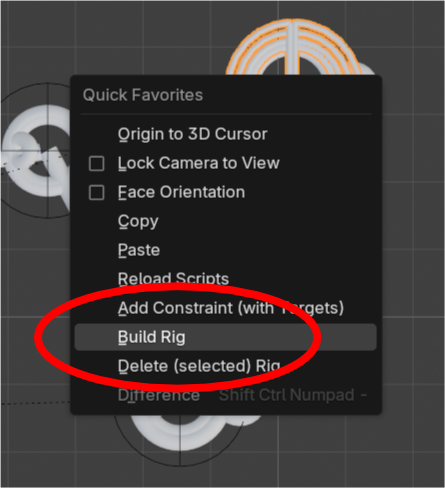
Recommended commands:
• Build Rig
• Delete (Selected) Rig
• Any other command you use frequently
This can significantly speed up the iteration process when experimenting with mechanisms.
Don't Be Afraid to Start Over
Mechanism design is highly iterative.
If a mechanism becomes overly complicated or behaves unexpectedly, it is often faster to delete it and rebuild it from scratch than to spend a long time fixing a problematic design.
Changing the Rotation Plane with SliderN
SliderN can be used to transfer motion into a different rotation plane.
After placing a SliderN, the next widget must usually be rotated to match the orientation of the SliderN output ring.
A common workflow is:
• Create the SliderN.
• Place the next Connector.
• Rotate the Connector by 90° around its X-axis.
• Continue building the chain in the new rotation plane (Orthogonal View, e.g. Front, Numpad 1)
This allows motion to be transferred cleanly between different linkage orientations.
Learn by Modifying Existing Mechanisms
The included presets are often the fastest way to understand how widgets interact.
Create PinJoins, move pivots, change linkage lengths and rebuild the rig.
Even small adjustments can produce dramatically different mechanical behavior, making experimentation one of the most effective ways to learn wk_mechanics.
Create Widgets
The widgets are the building blocks of every mechanism in wk_mechanics.
A mechanism usually starts with a ChainStart, followed by Connectors, Sliders or Seesaws, and is completed with specialized elements such as PenJoints, CAMs or Rods.
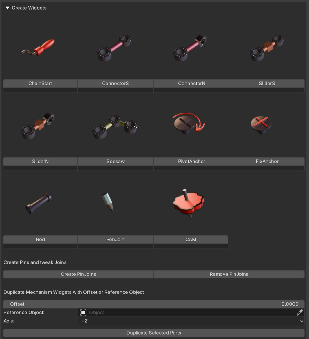
ChainStart
The starting point of every mechanism.
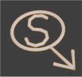
A ChainStart acts as the driving element („Motor“) of a linkage chain and provides the initial motion that powers the mechanism.
Every independent linkage chain must begin with a ChainStart.
Typical use cases:
• Crank mechanisms
• Drawing machines
• Walking machines
• Automata
Important:
A rotating ChainStart should not be connected directly to a Seesaw or Slider. Insert at least one Connector between them to avoid mechanical locking.
ConnectorS
A standard linkage with two connection points.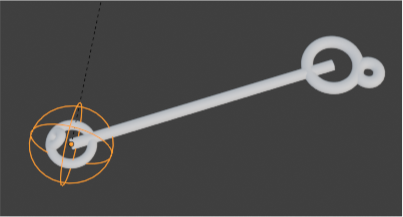
Connectors transfer motion between different parts of a mechanism and are the most commonly used widget.
ConnectorN
An experimental variation of the standard connector.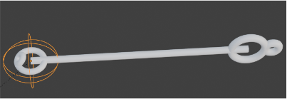
ConnectorN was originally intended for alternative motion transfer and orientation changes within a linkage chain. Depending on the mechanism, it can be useful when the default ConnectorS does not provide the desired linkage arrangement.
Note:
ConnectorN is an experimental widget. Most mechanisms can be built using ChainStarts, Connectors, Seesaws and Sliders. ConnectorN is provided for advanced or unusual linkage configurations and has not been tested as extensively as the other widgets.
SliderS
A slider that constrains movement along a linear path.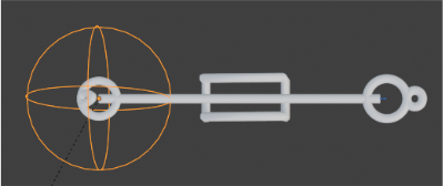
SliderS is useful when rotational motion must be converted into linear motion while remaining on the same working plane.
Typical use cases:
• Pistons
• Followers
• Linear actuators
• CAM followers
SliderN
A directional slider used to redirect motion.
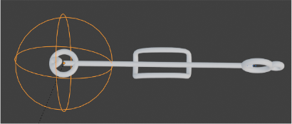
Unlike SliderS, SliderN is commonly used when motion needs to be transferred into a different direction.
The Writer Vertical preset demonstrates a typical SliderN application.
Important: Align all following widgets to the new rotation! Usually it’s local X=90 rotation!
Typical use cases:
• Vertical motion transfer
• Compact linkage layouts
• Motion redirection
Seesaw
A versatile multi-connector widget.
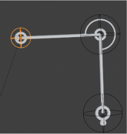
A Seesaw can function as a classical lever when attached to a PivotAnchor (usually, PivotAnchor is placed on Seesaw Middle), but it can also be used as a simple multi-connection linkage element without a pivot.
Because of its center connection point, it is often used where a standard connector would not provide enough flexibility.
Typical use cases:
• Levers
• Motion distribution
• Multi-connection joints
• Drawing machines
PivotAnchor
Creates a fixed rotational pivot.
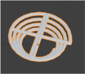
PivotAnchors are typically combined with Seesaws to create lever mechanisms, but they can also serve as fixed rotational supports elsewhere in a mechanism, e.g. end of a chain of two connectors.
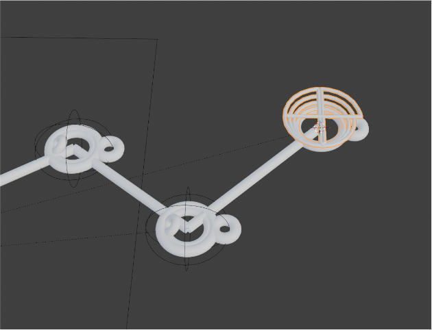
Typical use cases:
Lever pivots
Fixed joints
Rotational supports
FixAnchor
Creates a fixed connection point.
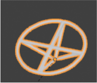
Unlike a PivotAnchor, a FixAnchor does not rotate and serves as a completely stationary anchor for the mechanism.
Typical use cases:
• Fixed mounting points
• Ground references
• Static supports
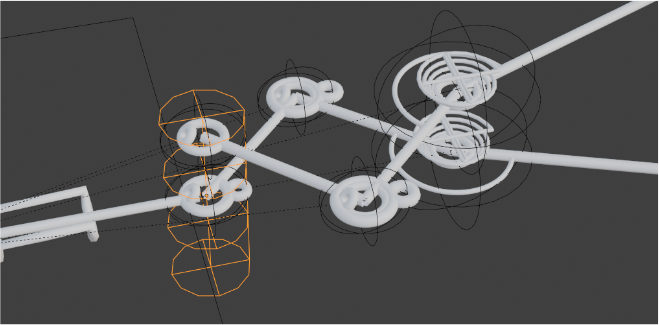
Rod
Creates a shared axle between linkage systems.
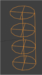
Rods are used to transfer motion between different Z-levels and reconnect separate linkage chains.
This allows the construction of realistic multi-layer mechanisms similar to physical laser-cut assemblies, where moving parts must pass over or under each other before merging again.
Typical use cases:
• Multi-layer mechanisms
• Shared axles
• Motion transfer between layers
Troubleshooting: If a Rod connection does not behave as expected, try moving the Rod to a different position in the mechanism. The same motion transfer can often be achieved at several points in a linkage chain, and some locations may produce more stable results than others.
PenJoin
Defines the output point of a mechanism.
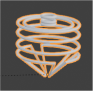
A PenJoin is typically attached to the end of a drawing machine and represents the point that traces a path.
It can be animated along a curve for CAM generation or used directly for drawing simulations.
Typical use cases:
• Drawing machines
• Motion tracing
• CAM generation
CAM
Defines the location and rotational axis of a CAM wheel.
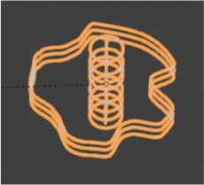
CAM widgets are used together with CAM Record to generate physical CAM profiles from mechanism motion.
The resulting CAM can later drive followers in real-world mechanical systems.
Typical use cases:
• Automata
• Drawing machines
• Motion programming
• Mechanical sequencing
Create Pins and Tweak Joints
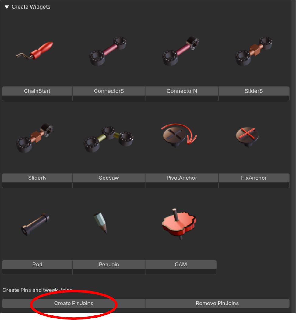
Create PinJoins
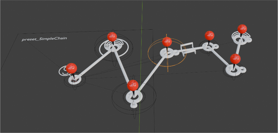
Creates editable control points at all major joints of the mechanism.
PinJoins make it easy to modify proportions, link lengths and pivot positions without manually reconnecting widgets.
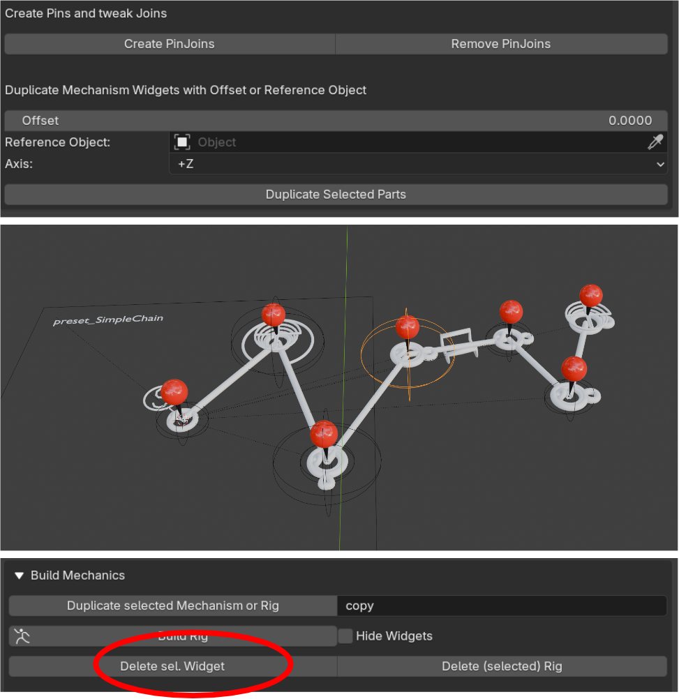
After editing, rebuild the mechanism using Build Rig to test the changes.
Remove PinJoins
Removes all PinJoin helper objects from the mechanism.
Deleting the PinJoins does not undo any modifications you made. All changes to link lengths, pivot positions and mechanism proportions remain part of the mechanism.
After removing the PinJoins, the mechanism can be rebuilt normally using Build Rig.
Duplicate Mechanism Widgets
These tools allow selected widgets to be duplicated with an offset or relative to another object.
Offset
Defines the duplication distance.
Reference Object
Uses another object as a positional reference for the duplication. The offset is applied only along the mechanism's designated "up axis" (defined by the selected Axis setting). This makes it easy to create additional mechanism layers with a precise and predictable spacing.
A common use case is creating a second linkage level directly above or below an existing mechanism while maintaining exact alignment between both layers. See preset „Writer“, „Writer Vertical“ or „Scissors“.
Axis
Defines the duplication direction.
Duplicate Selected Parts
Creates copies of the selected widgets using the specified settings.
Combined with Reference Object, this allows entire sections of a mechanism to be duplicated onto another layer with precise spacing and alignment.
Build the mechanism once, duplicate it, then add only the parts that differ between the layers. This is often much faster than constructing multiple identical linkage systems from scratch.
For example, the Writer Vertical preset uses duplicated linkage sections because both arms remain identical until they reach the point where their motion is combined. This significantly reduces setup time and ensures both sides stay perfectly synchronized.
Build Mechanics
The Build Mechanics module converts widget layouts into functional rigs and provides tools for testing, modifying and duplicating mechanisms.
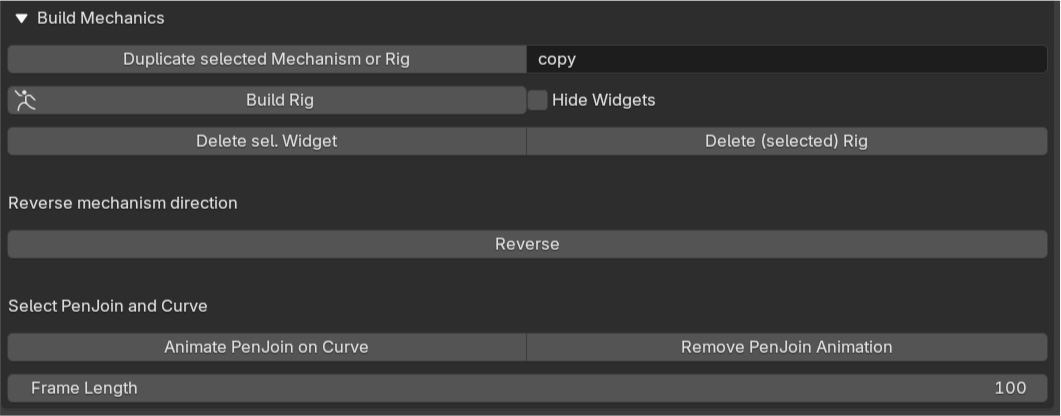
In most workflows, this is the stage where a designed mechanism becomes an animated and fully functional system.
Duplicate Selected Mechanism or Rig
Creates a complete copy of the selected mechanism or rig.
The new copy receives automatically updated names using the specified suffix, allowing multiple versions of the same design to exist in the scene without naming conflicts.
Depending on the selected object, either the widget mechanism or the generated rig collection will be duplicated.
Typical use cases:
• Creating design variations
• Building mirrored or alternative versions (yes, you can mirror a mechanism by scaling x = -1 and then build rig!)
• Preserving a working version before experimentation
• Creating multiple drawing machines or walkers based on the same design with different variations
Build Rig
Converts the widget-based mechanism into a fully functional animation rig.
All mechanical relationships are generated automatically, allowing the mechanism to be tested and animated directly inside Blender.
Whenever widgets have been added, removed or modified, the rig should be rebuilt.
Hide Widgets
Hides the internal widget collection (__WKMECH).
This can make the viewport cleaner and easier to work with once the rig has been generated.
The widgets are not deleted and can be shown again whenever further editing of the mechanism is required.
Delete Selected Widget
Removes the selected widget (including the whole hidden hierarchy) from the mechanism.
This is useful when you’ve created a wrong widget.
Delete (Selected) Rig
Deletes the generated rig collection while keeping the original widget mechanism intact.
This is useful when major changes need to be made to the widget setup before generating a new rig.
Reverse Mechanism Direction
Reverse
Reverses the operating direction of the mechanism (doesn’t work for all mechanisms!).
This is particularly useful for CAM generation and drawing machines, where a mechanism may need to follow a path in the opposite direction.
Select PenJoin and Curve
These tools are primarily used for CAM creation and drawing machines.
Select a PenJoin and a Curve, then use the controls below to generate animation data.
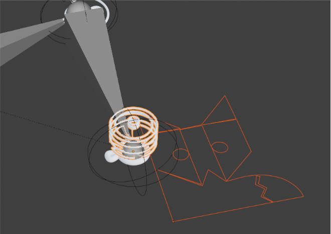
Animate PenJoin on Curve
Creates an animation that moves the selected PenJoin along the selected curve.
The resulting motion can later be recorded and converted into CAM profiles using the CAM Record workflow.
This is one of the key tools for creating CAM-driven drawing machines.
Remove PenJoin Animation
Removes the animation generated by Animate PenJoin on Curve and resets the rig to default pose.
This allows a different curve or animation setup to be created without rebuilding the mechanism.
Frame Length
Defines the number of frames used for the generated PenJoin animation.
Higher values create smoother and more detailed motion, while lower values can be useful for quick testing and iteration.
CAM Record
The CAM Record module is used to generate physical CAM profiles from mechanism motion.

Instead of designing a CAM shape manually, wk_mechanics records the movement of a follower and automatically creates a CAM contour that reproduces the same motion when rotated.
This workflow is particularly useful for drawing machines, automata and other mechanisms where complex movements need to be converted into physical CAM-driven motion.
CAM Pivot Object
Select the CAM widget that acts as the rotational center of the generated CAM.
The position of this widget determines where the CAM will be created.
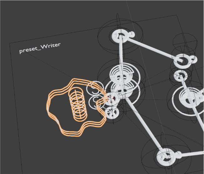
Important: The distance between the CAM Pivot Object and the follower directly affects the size of the generated CAM.
Larger distances result in larger CAMs, which often produce smoother and more precise follower movement.
Follower List
To add followers:
• Select the desired follower bone(s) in Pose Mode.
• Press the "+" button.
• The selected bones will be added to the follower list.
During CAM Record, wk_mechanics analyzes the motion of these bones and generates matching CAM profiles.
Multiple follower bones can be recorded simultaneously. This makes it possible to create coordinated CAM systems where several CAM wheels work together to reproduce complex mechanical motion.
For example, a drawing machine may use separate followers to control the pen's movement along two independent axes. The resulting CAM pair can reproduce the complete drawing motion when both movements are combined.
Samples
Defines how the recorded motion is distributed around the CAM wheel.
If the number of Samples matches the frame count used for the PenJoin animation, the complete follower motion will be mapped across the full CAM rotation.
For example:
100 animation frames + 100 Samples → the entire motion is distributed across 360°.
100 animation frames + 200 Samples → the entire motion is compressed into 180° of the CAM rotation.
The remaining part of the CAM becomes a circular arc, causing the follower to remain stationary during that section of the rotation. This behavior can be used intentionally to create dwell periods, where a mechanism pauses before continuing its movement.
Degrees
Defines the angular range used during CAM recording.
A value of 360° records a complete rotation.
Lower values can be used when only a portion of a rotation should be converted into a CAM profile.
CAM Record
Generates CAM geometry from the recorded follower motion.
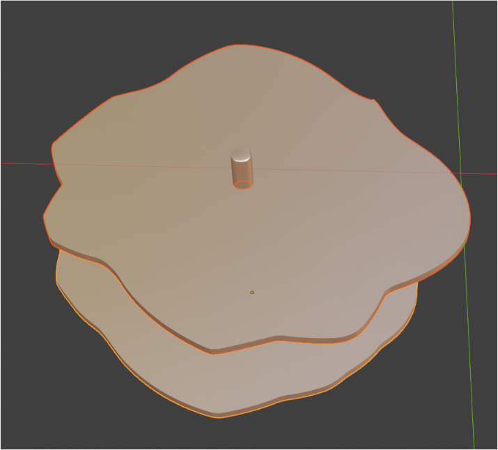
Typical Workflow
Build and test a mechanism.
Create a PenJoin animation on reversed mechanism or another motion source.
Select a CAM Pivot Object.
Add the follower bones (pose mode) to the list.
Choose the desired sample count and angular range.
Press CAM Record.
Use the generated CAMs to drive the mechanism physically.
Test / Sim
Before manufacturing a CAM, it is often useful to verify that the generated profile reproduces the intended motion.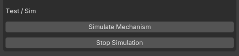
The simulation tools allow the follower to be constrained to the generated CAM profile and driven by its rotation. This provides a quick way to validate the resulting movement before exporting blueprints or manufacturing parts.
Simulate Mechanism
Starts a simulation using the generated CAM profiles.
Followers are constrained to the CAM curves and driven by CAM rotation, allowing the user to verify that the resulting motion matches the intended design.
Stop Simulation
Stops the active CAM simulation and removes the temporary simulation setup.
Use this after testing or before generating new CAM profiles.
Blueprint Mechanism
The Blueprint Mechanism module converts a mechanical widget setup into fabrication-ready parts.
Unlike the rigging workflow, Blueprint Mechanism focuses on creating physical components that can later be exported as SVG files and manufactured using laser cutters, CNC machines or other fabrication methods.
The generated blueprint parts remain fully editable, allowing the mechanism to be refined before creating the final manufacturing layout.
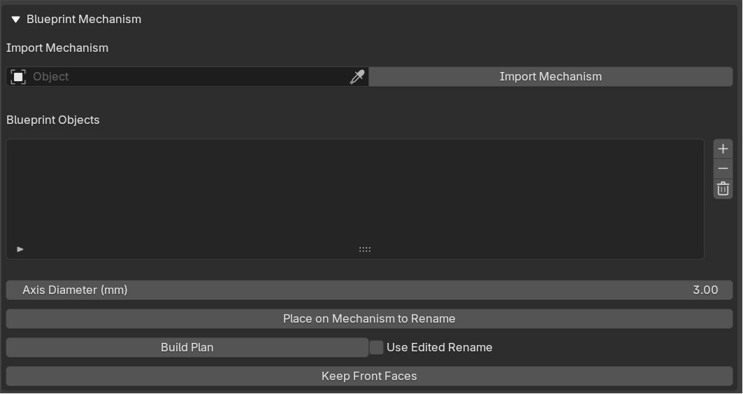
Import Mechanism
Select any widget that belongs to the mechanism you want to convert into blueprint parts.
After selecting a widget, press Import Mechanism.
wk_mechanics will automatically detect the entire mechanism and prepare it for blueprint generation.
Blueprint Objects
This list contains all blueprint parts that belong to the imported mechanism.
Only mechanical components are included in this list. Helper widgets such as ChainStarts or PivotAnchors are not converted into physical parts.
Each entry represents a blueprint object that can later be edited, renamed, duplicated or removed before creating the final layout.
Axis Diameter (mm)
Defines the diameter of the holes generated at all pivot and connection points.
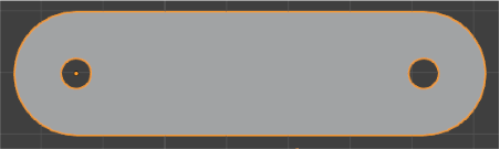
These holes are automatically created wherever mechanical joints or rotational axes are required.
Adjust this value to match the diameter of your intended shafts, bolts, pins or other hardware.
Place on Mechanism to Rename
Generates the blueprint parts directly on top of the original mechanism. This step is optional but highly recommended.
The generated blueprint objects can now be:
• Renamed
• Edited
• Reshapedv
• Duplicated
• Deleted
Any modifications made at this stage will be preserved when the final manufacturing layout is generated.
This allows the blueprint to be customized without affecting the original widget mechanism.
Build Plan
Creates the final fabrication layout.
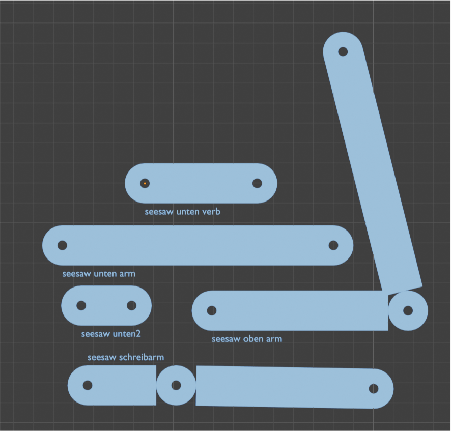
All blueprint parts are flattened onto the plane at the current 3D Cursor position and arranged for manufacturing.
If blueprint parts were renamed, edited, duplicated or deleted after using Place on Mechanism to Rename, those changes will be included automatically.
This makes it possible to customize the fabrication design before generating the final plan.
Typical Workflow
• Import a mechanism.
• Generate blueprint parts using Place on Mechanism to Rename.
• Modify the generated parts if desired.
• Press Build Plan and arrange them to your liking.
• Export the resulting layout as SVG.
Use Edited Rename
When enabled, names that were changed after Place on Mechanism to Rename are preserved and used during Build Plan generation.
This is useful for organizing complex mechanisms or assigning meaningful names to fabrication parts. All exported parts will be SVG layers with the respecting names.
Keep Front Faces
Removes the back side of the generated parts and keeps only the front-facing geometry.
This can be useful when preparing parts for SVG export or laser-cut workflows where only a single outline surface is required.
Export SVG
The Export SVG module converts selected blueprint parts into SVG files that can be used for laser cutting, CNC workflows, vector editing or other fabrication processes.
The export is generated from the current viewport projection, allowing Blender to function as a simple CAD-style layout environment.
Important:
For accurate dimensions, switch to an Orthographic Top View before exporting.
Select Mesh Objects to Export
Select the blueprint parts you want to include in the SVG export.
Only the currently selected mesh objects will be exported.
This allows individual components, subassemblies or complete fabrication layouts to be exported as needed.
Millimeters Per Blender Unit
Defines the scale conversion between Blender units and real-world millimeters.
The default value of 1000 assumes that:
• 1 Blender Unit = 1 Meter
• 1 Blender Unit = 1000 Millimeters
Adjust this value only if your project uses a different unit scale.
Stroke Width (mm)
Defines the line thickness written into the SVG file.
This setting mainly affects visibility and usability when the SVG is opened in a vector editing application.
A value around 0.1 mm usually provides a good balance between readability and precision.
• Very thick lines can make the design difficult to inspect and edit because details become obscured.
• Extremely thin lines can be difficult to see and select.
• Moderate line widths make it easier to review and refine the design after export.
In many workflows, the generated blueprint parts primarily serve as construction guides. They provide the required link lengths, pivot locations and hole positions needed to build the mechanism.
While the blueprint meshes can be fully edited and finalized inside Blender, many users prefer to use them as references in a vector editing application. A common workflow is to redraw the final parts in software such as Affinity Designer or Inkscape while keeping the generated hole locations and dimensions from the blueprint.
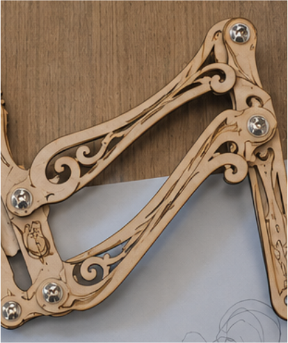
This approach often provides greater flexibility when adding decorative details, manufacturing features, labels or stylistic design elements before fabrication.
Export to SVG
Creates an SVG file from the currently selected mesh objects.
Start Here: Explore the Presets
The fastest way to learn wk_mechanics is by opening and modifying the included presets.
Writer
Creates a CAM-driven drawing machine.
Good for learning:
ChainStarts
Connectors
Seesaws
PenJoin
Multi-layer mechanisms with Rod widgets
CAM generation
Writer Vertical
Demonstrates vertical motion transfer.
Good for learning:
Using SliderN to change the direction of motion transfer.
Walker
Inspired by mechanical walking machines and Theo Jansen’s „Strandbeest“.
Good for learning:
Linkage design
Motion amplification
Coordinated movement
Scissors
Demonstrates constrained expansion and contraction.
Lever
Simple example showing rotational motion transfer.
Simple Chain
Minimal mechanism for understanding widget relationships.
Experiment with the Presets
The presets are not meant to be used as fixed examples. They are designed to be explored, modified and broken apart so you can understand how the mechanisms work.
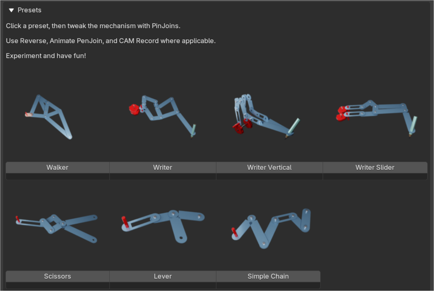
To adjust a preset, click Create PinJoins. This creates editable control points at all important joints of the mechanism.
You can now move the PinJoins to change link lengths, pivot positions and the overall behavior of the mechanism. Since the widgets remain constrained to the PinJoins, the mechanism can be reshaped without manually reconnecting individual parts.
After making changes, click Build Rig to rebuild the mechanism and test the new motion.
This is often the fastest way to learn how different linkages behave. Try changing proportions, moving pivots or extending chains and observe how the resulting motion changes.
Tip: Start with small adjustments. Even minor changes in linkage geometry can produce dramatically different mechanical behavior.
Support:
You have read the entire documentation, tried the presets, rebuilt the mechanism from scratch, questioned your sanity, and it still doesn't work?
Send me an email:
[email protected]
I'll do my best to help.
Have questions about this product?
Login to message
| Blender Extension Compatible | Yes |
| Dev Fund Contributor | |
| Published | 4 months ago |
| Blender Version | 5.1 |
| Extension Type | Add-on |
| Render Engine Used | Cycles, Eevee |
| License | GPL |
Discover more products like this
linkages maker strandbeest cam design drawing machine cam automata Mechanism kinetic art linkage engineering mechanics automata