Archisection Pro
 GPolygon Design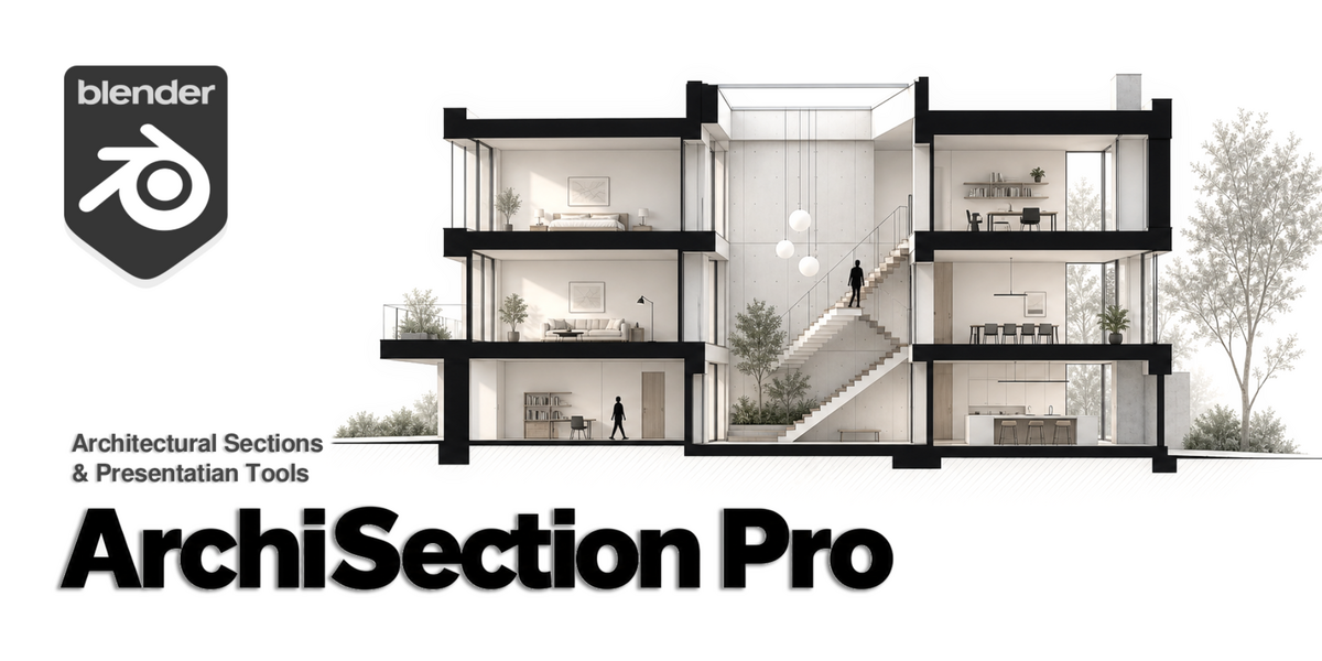

ArchiSection Pro Documentation
Installation and user guide for version 1
ArchiSection Pro helps you create architectural sections and compose presentation drawings inside Blender. This guide takes you from installing the add-on and preparing a model to placing annotations, saving multiple sections and exporting scaled sheets.
Start with Installation, Prepare your scene and Create your first section. Use the remaining chapters as a reference while working. Button names in bold match the English interface of version 1
Contents
1 What the add-on includes
2 Installation
3 Prepare your scene
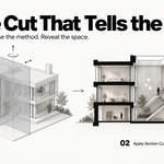
4 Create your first section
5 Section cutting and manual poché
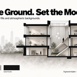
6 Ground and topography
7 Entourage silhouettes
8 Sky and city backgrounds
9 Elevations and section titles
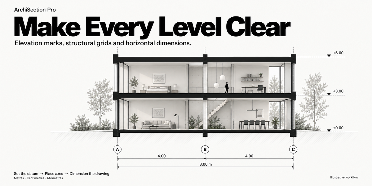
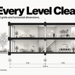
10 Grid axes and dimensions
11 Manage multiple section views
12 Sheet layout and drawing styles
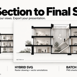
13 Export PNG and SVG sheets
14 Troubleshooting
15 Final checks and support
1 What the add-on includes
Section cutting: an editable section plane, reversible cutting direction, Boolean cuts with poché, and hollow camera clipping.
Manual poché: two-click rectangular patches with individual enable and disable controls.
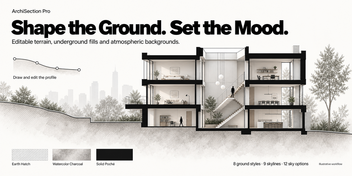
Ground and topography: flat ground placement, editable custom profiles, ground line thickness and underground fill depth.
Eight underground styles: painterly washes, strata, mineral grain, earth hatching, gradients and solid black.
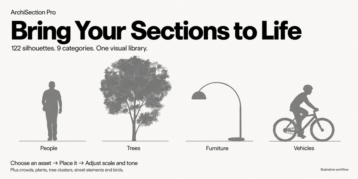
Entourage: 122 image-based silhouettes across nine categories, with interactive placement, foreground and background layers, horizontal flipping and grayscale styling.
Backgrounds: nine city skyline presets and twelve sky options.
Drawing annotations: elevation marks, a reference datum, section titles, grid axes and horizontal dimensions.
Section Views: multiple named cuts with their own presentation settings and drawing objects.
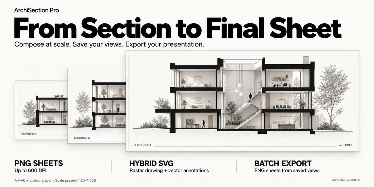
Sheet composition: A4 to A0 and custom paper sizes, portrait and landscape orientation, five drawing scale presets and a viewport sheet frame.
Export: PNG sheets, hybrid SVG sheets and batch PNG export of saved sections.
You provide the architectural model. The silhouettes are presentation assets placed on planes; they are not fully modeled 3D people, trees or furniture. ArchiSection Pro supports architectural communication and drawing composition; it does not replace a complete CAD or BIM documentation system.
2 Installation
Requirements and compatibility
The version 1 manifest accepts Blender 4.2.0 and later. Recorded technical checks for this release were performed on Windows with Blender 5.0.1. Other Blender versions and operating systems have not been verified for this release; the minimum version in the manifest is not a guarantee of compatibility with every later version.
No external Python packages, separate accounts or network services are required for the add-on's tools. You need a local folder where Blender can save exported drawings. Large scenes and high-resolution sheets need more processing time and memory.
Install the ZIP package
1. Download the release ZIP. For this version, the package is named archisection_pro-1.zip. Keep it zipped.
2. Open Blender and choose Edit > Preferences.
3. Open Get Extensions and use the menu at the top right to choose Install from Disk. The command may also be available through the Add-ons menu, depending on Blender's version.
4. Browse to the downloaded ZIP and select it. Follow Blender's installation prompt.
5. Search for ArchiSection Pro in Preferences and ensure it is enabled.
6. Close Preferences and move the pointer over the 3D Viewport.
7. Press N to open the sidebar, then select the ArchiSection tab.
The initial panel should show Create Section Plane. If you are in a different editor, such as the Shader Editor, switch that area to the 3D Viewport first.
Blender's official installation reference: Get Extensions in the Blender Manual.
Updating an existing installation
Save your project and a backup before updating. Install the new release ZIP through Install from Disk, follow Blender's replacement or update prompt, then restart Blender and confirm that the intended version is enabled. Avoid enabling both an old legacy installation and the new extension at the same time.
After an update, open a copy of an existing project and check one section, its annotations and a small export before continuing production work. Keep the original project backup until those checks are complete.
3 Prepare your scene
Model size and scene units
Scaled export requires Scene Properties > Units > Unit Scale = 1.0. The drawing workflow treats one Blender unit as one metre. Setting the unit system to Metric makes these dimensions easier to read.
Check a known dimension before creating the section. A room that is 5 metres wide should span 5 Blender units. If an imported model arrives at the wrong scale, correct the model's dimensions before building the drawing. Simply changing the scene's Unit Scale does not repair incorrectly sized geometry.
Version 1 rejects sheet export at other unit scales to avoid incorrect printed dimensions. Dimension display options such as cm and mm change how measurements are written; they do not change this export requirement.
Geometry preparation
For Boolean mode, use clean, closed meshes wherever practical. Open surfaces, intersecting faces and damaged imported geometry can produce incomplete or unexpected cuts. Review the geometry and modifier stack if a cut fails. Solver recovery can help some models, but it cannot guarantee a correct result on every mesh.
For models that are unsuitable for Boolean cutting, try Clip (Hollow). This gives a camera-clipped section without generating solid caps. Import models from other applications into Blender before using the add-on; ArchiSection Pro is not itself a dedicated CAD or BIM importer.
Working view
Start in Object Mode with a usable 3D Viewport. Keep Blender's status bar visible: interactive tools show placement, snapping and completion instructions there. Save the scene as a .blend file before starting a drawing set.
Use the add-on's orthographic section camera for sheet composition. Ordinary viewport orbiting is useful for inspecting the model, but the exported drawing is framed by the section camera and the chosen physical sheet settings.
4 Create your first section
The following sequence creates a basic A3 section sheet. Use an existing building model with dimensions checked as described above.
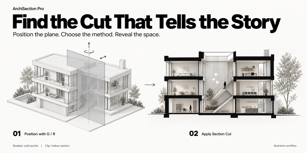
1. Create the plane. Open ArchiSection and click Create Section Plane. A visible plane and direction indicators appear in the scene.
2. Position the cut. Use G to move the plane and R to rotate it through the part of the building you want to show. Click Flip Cut if the viewing direction is reversed.
3. Choose the method. Select Boolean (Poché) for suitable closed meshes, or Clip (Hollow) for a camera-clipped view. In Boolean mode, choose the desired black or gray poché treatment.
4. Apply the section. Click Apply Section Cut. Use View Camera to inspect the resulting section. The positioning plane should no longer be part of the completed drawing.
5. Set the sheet. In Sheet Layout & Export, choose A3, Landscape, 1:100 and a modest preview DPI. Turn on Show 3D Sheet Frame and check that the building fits.
6. Establish the datum. In Elevation Marks, click Set ±0.00 Datum, then click the floor or ground reference you want to use as zero.
7. Add ground. In Ground & Topography, choose Flat Ground, set or place its elevation, choose a Hatch Style, and use Generate Ground & Hatch as needed.
8. Add context. In Entourage Silhouettes, choose a category and thumbnail, select the desired layer and click Click Drop Silhouette. Move the preview into place and left-click.
9. Add labels. Use Add Level Mark for important floor levels. Enter a section title in the main panel and click + Title.
10. Export a preview. Choose Flat Textures (Unlit) in Drawing Style, click Export PNG Sheet, and select a filename and destination folder.
Open the exported image and check the cut, framing, contrast and annotation positions. Refine the drawing before raising the DPI for final output. For this example, a correctly modeled 1 metre length at 1:100 should measure 10 millimetres on an actual-size print.
5 Section cutting and manual poché
Boolean and Clip modes
Boolean (Poché) uses a cutter and modifiers to produce the section. Suitable closed geometry can produce solid cut faces with the selected poché treatment. The source mesh is not directly sliced by deleting its vertices through this workflow; manually applying modifiers is a separate Blender action.
Clip (Hollow) uses the section camera's near clipping plane. It does not create Boolean cut faces or solid caps. Use it when a hollow section is appropriate, or when imported geometry is difficult to cut reliably. Inspect Clip results through View Camera, since the camera is what defines the clipping view.
Edit an existing cut
1. Click Edit Plane in the active section panel.
2. The current cut and section camera are removed temporarily, and the positioning plane becomes visible again. This is the expected editing state.
3. Move or rotate the plane with G and R. Adjust the method or direction if required.
4. Click Apply Section Cut again, then return to View Camera.
5. Check ground, silhouettes and annotations against the revised cut. Presentation objects are not a substitute for reviewing the new drawing.
6. If the section is stored in the library, select its entry and use Update after applying the revised cut.
Add a manual poché patch
Use Draw Poché Box (2-Clicks) for a local graphic correction where a rectangular solid fill is useful.
1. Work in the active section view and click Draw Poché Box (2-Clicks).
2. Click the first corner of the patch.
3. Move the pointer to size the rectangle, then click the opposite corner.
4. Review the patch in the drawing. Use its Disable or Enable button in the main panel to compare the result with and without the patch.
Press Esc or right-click to cancel an unfinished patch. A patch is a drawing element, not a repair to the underlying building mesh. Check that it does not hide an opening or detail that should remain visible.
Removing a section
The main panel's Remove command cleans up the active section setup, including generated section elements. Use it when you intend to remove that setup, not merely leave the camera view. To remove one stored view and its associated drawings, use the minus button in Section Views instead. Save the project before cleanup, especially when working with several views.
6 Ground and topography
Open Ground & Topography after applying a section. Choose a ground mode, establish the profile, then adjust the line and underground fill.
Place flat ground
1. Select Flat Ground.
2. Click Place Flat Ground (Click).
3. Move the pointer to the desired height in the section. Watch the elevation preview and snapping feedback.
4. Left-click to place the ground, or press Esc to cancel.
5. For a precise numeric reference, use Elevation (Z). The Cursor button reads the 3D cursor's Z height.
6. Set Hatch Style, Line (m) and Depth (m). Use Generate Ground & Hatch to build or rebuild the result when needed.
Flat ground and elevation marks use the same ground-level value. Changing this value also changes the reference used by level labels. If you need a varying terrain profile while keeping one fixed elevation datum, use a custom curve for the terrain.
Draw a custom ground profile
1. Select Custom Curve and click Draw Ground Line (Click-to-Draw).
2. Position the first preview point and left-click.
3. Continue clicking points along the desired profile. Draw consistently across the section in one horizontal direction.
4. Add changes in height for slopes or steps. Use the axis locks below when you need a straight horizontal or vertical segment.
5. After at least two points, press Enter to finish. Space or right-click also finishes a valid profile. Esc cancels the drawing operation.
6. Use Generate Ground & Hatch if the profile needs to be rebuilt into its ground line and fill.
Profiles that double back horizontally are not supported. Keep the contour ordered across the sheet. The underground fill follows the profile above and has a horizontal lower boundary.
Ground drawing controls
Left-click: add a point; in Flat Ground placement, commit the height.
Enter: finish a custom profile with sufficient points.
Esc: cancel the current drawing operation.
Backspace or Ctrl+Z: remove the most recent custom-profile point.
X: toggle a horizontal segment lock.
Z or Y: toggle a vertical segment lock in the drawing plane.
C: clear the segment lock.
S or Shift+Tab: toggle Blender's snap setting during ground drawing.
Ctrl: temporarily reverse the current snapping state.
Green preview feedback indicates a snap; yellow indicates free placement. These keys apply while the ground drawing tool is running, not to ordinary Blender editing outside that tool.
Edit or replace ground
Click Edit Points to enter Edit Mode on the custom curve. Select its points, move them with G, then return to Object Mode and rebuild with Generate Ground & Hatch. Reset Curve resets the custom profile rather than simply leaving Edit Mode. Delete Ground & Curve removes the generated ground and its curve.
Line (m) controls the ground profile's thickness in scene metres; Depth (m) controls the underground region. Existing ground responds to these settings and the hatch selection. Inspect the result after substantial edits.
Underground style guide
Oil Painting Wash (Soft): a soft painterly base for an illustrated section.
Sedimentary Strata: layered ground texture with a geological character.
Watercolor Charcoal: a subdued charcoal and watercolor treatment.
Sandstone & Mineral Grain: fine grain and mineral texture.
Warm Ochre Gouache: a warmer earth-toned wash.
Earth Hatch (45°): diagonal architectural earth hatching.
Gradient Fade: a ground fill that fades toward the background.
Solid Poché (Black): a strong monochrome underground mass.
Choose the style in relation to annotation readability. A visually strong fill can compete with dimension text, so check a small export before committing to the final sheet.
7 Entourage silhouettes
Browse and place assets
The gallery contains 122 image-based silhouettes in People, Crowds & Groups, Trees, Tree Clusters, Plants & Pots, Furniture, Urban & Street, Vehicles & Bikes, and Birds.
1. Open Entourage Silhouettes and choose a Category.
2. Select an asset from the thumbnail gallery.
3. Check Foreground or Background. Changing to Trees or Tree Clusters automatically selects Background; other categories default to Foreground.
4. Set Scale and click Click Drop Silhouette.
5. Move the preview across the drawing and left-click to place it. Esc or right-click cancels an unplaced preview.
These assets sit on planes arranged for the section view. Judge their size and overlap through the section camera. They will not behave like fully modeled objects when viewed from arbitrary directions.
Repeated placement and ground placement
Enable Multi-Drop Mode to continue placing the selected asset on each click. Alternatively, hold Shift while clicking to continue placement. When finished, press Esc or right-click: already placed assets remain, while the current unplaced preview is removed.
On Ground (±0.00) places the selected asset at the datum ground height. This is not automatic alignment to every point of a sloping custom profile. For sloping terrain, use interactive placement and position the silhouette's base on the visible ground line.
Select an existing silhouette and use Flip Horizontal to change its facing direction. Move existing objects with Blender's transforms when necessary, keeping them aligned with the section composition.
Grayscale styling
Gray Tone ranges from 0 for black to 1 for white. Color Mix controls how strongly that tone replaces the asset's original image appearance: 0 keeps the original, while 1 applies the full silhouette tone.
These styling controls update entourage materials belonging to the current section. Treat them as controls for that section's entourage treatment, not as a guaranteed independent color adjustment for only the selected object. Use restrained contrast for background vegetation and stronger contrast for foreground figures when that improves readability.
8 Sky and city backgrounds
Open Sky & City Skyline. The city and sky controls can be enabled independently.
City skyline
Enable City Skyline Backdrop, choose a Style, then adjust Opacity and Height. The skyline is placed behind the architecture and background entourage. Its image scales from the bottom centre, helping the base remain visually grounded.
The nine presets are Skyscrapers & High-Rise, Urban Apartment Blocks (6-9 Fl), Boutique Townhouses (3-4 Fl), Pitched-Roof Village, Industrial Factory, Mixed Urban Density (3:1), Compact City (3:1), Low-Rise Residential, and Minimal High-Rise.
Atmospheric sky
Enable Atmospheric Sky Backdrop and choose Texture Style. The twelve options are Cloudy Watercolor, Blue Watercolor (Zenith), Blue Watercolor (Horizon), Monochrome Gray Mist, Soft Mist Grain, Deep Teal Storm (Zenith), Teal Storm (Horizon), Vertical Drips (Light), Vertical Drips (Deep), Misty Pine Forest, Mountain Valley, and Procedural Gradient.
Keep the building readable against the background. Review fine foliage, transparency and material appearance in the intended export style. The sky sits behind the skyline; it should support the drawing rather than become its strongest visual element.
9 Elevations and section titles
Set the reference datum
1. Open Elevation Marks and click Set ±0.00 Datum.
2. Hover over the desired reference point, such as the ground-floor slab.
3. Use S to toggle snapping during this tool if needed.
4. Left-click to set the datum, or press Esc/right-click to cancel.
You can also enter the reference Z value in the panel. A level label shows its marker's world Z minus the datum's world Z. For example, a marker at Z = 6.20 with a datum at Z = 3.00 reads +3.20 m.
Place level marks
Click Add Level Mark, move the preview to the required height and left-click. Hold Shift while placing to continue adding marks. S toggles snapping; X and Z/Y control horizontal and vertical locks, and C clears a lock. Esc or right-click ends or cancels the current placement preview.
Level labels update when marker objects move vertically or when the datum changes. This does not mean the markers are attached to slabs. After changing the building's floor heights, check and reposition the marks against the updated model.
Add a title
Type the desired section title in the main panel and click + Title to place a title below the drawing. Check that it fits within the sheet alongside the dimensions. Use distinct section names early in a multi-view project so each drawing is easy to identify in the library and exported filenames.
10 Grid axes and dimensions
Open Grid Axes & Dimensions with an active section. Decide the paper scale early, because Text (mm) is intended to control the printed annotation size.
Detect or place axes
Choose lettered or numbered grid labels in Structural Grid. Set Min Spacing and Text (mm), then click Detect Axes. Detection proposes axes from geometry crossing the cut; it is not a semantic reading of the building's official structural grid.
Review the result. A higher Min Spacing can reduce nearby duplicate proposals; a lower value can retain more closely spaced candidates. If the automatic result is unsuitable, use Clear Axes, then place the intended axes with Place by Hand.
During manual placement, move the preview to the desired position and left-click. Use Shift-click to continue placing, and Esc or right-click to finish. The tool provides cursor and snapping feedback. Inspect the final axis positions against the actual structural elements.
Generate dimension chains
1. Create at least two axes.
2. Choose m, cm or mm in the Dimensions controls.
3. Set Offset to position the dimension chain below the ground line.
4. Set Text (mm) for the printed label size.
5. Click Dimension Axes to generate consecutive spans and an overall dimension.
After moving or editing an axis, click Dimension Axes again to regenerate measurements from the current positions. Do not assume an existing chain has automatically rebuilt. Recheck the chain after changes to units, scale, text size or ground composition.
Measure two points
Click Measure 2 Points, then click the first and second locations on the section plane. The tool creates a horizontal projected dimension between those points. Its vertical placement comes from the first point.
This tool does not report an arbitrary 3D distance or the diagonal distance between points at different heights. For floor levels, use elevation marks. Press Esc or right-click before the second point to cancel.
Contrast and cleanup
The add-on can choose black or white annotation ink based on sampled ground imagery. This is not a complete analysis of every rendered material. If the text is difficult to read, adjust the offset, printed text size or underlying hatch, then export a preview.
Use Clear Dims to remove dimensions while retaining the axes. Clear Axes removes axes; keep any remaining dimensions under review because their generating references have changed.
11 Manage multiple section views
Register the first section
After creating your first cut, open Section Views. If the list is empty, click Register Section in List (A-A). This registers the current drawing as the first entry; it does not immediately create a second cut.
Use + to add the next section. The add-on stores and hides the current section's drawing objects, creates a new entry and displays a plane for the new cut. Position it and click Apply Section Cut. A new view starts with fresh presentation settings, so compose its ground and backgrounds deliberately.
Recall and update a view
Select an entry and click Go To Section to restore its cut and presentation. The previous view's drawing objects are hidden, and the selected view appears through the section camera.
To save a revision explicitly, first go to the correct view, make and apply the changes, then select that same entry and click Update. Update writes the current cutting plane and settings into the selected entry; verify the selection before using it.
What is independent and what is shared
Saved views retain their cutting plane and core sheet settings, plus presentation settings such as ground, backdrops, entourage styling, DPI and drawing style. Their associated drawing objects are shown or hidden when changing views.
The underlying architecture remains shared. If you change a wall or floor in the source model, review every affected section. Do not treat a saved view as a frozen copy of the building or as an automatically updated full technical drawing.
Use the up/down arrows to reorder entries. The minus button removes the selected stored section and its drawings. Save the .blend file to retain the section set between Blender sessions.
12 Sheet layout and drawing styles
Paper and orientation
Open Sheet Layout & Export and choose A4, A3, A2, A1, A0, or Custom Size. Custom dimensions use W (mm) and H (mm). Select Landscape or Portrait, then choose a scale: 1:20, 1:50, 1:100, 1:200, or 1:500.
Click Show 3D Sheet Frame to preview the physical sheet boundary. The frame responds to the paper and scale settings. Check the overflow warning: if the drawing or annotations exceed the sheet, use a larger paper size or a smaller drawing scale. For example, changing from 1:100 to 1:200 makes the building occupy less space on the same paper.
The exporter uses the orthographic section camera and the chosen sheet scale. Use the add-on's sheet controls instead of relying on a manually changed camera scale that may be replaced during export.
Resolution and memory
DPI controls raster detail, not architectural scale. The available range is 72 to 600 DPI. Start with a lower-resolution preview; choose the final resolution after checking composition and labels. The panel shows the resulting pixel dimensions.
Larger paper at the same DPI creates more pixels. Doubling DPI in both directions creates approximately four times as many pixels. Version 1 rejects requests above Blender's supported image dimension or 150 million pixels. Even smaller images may be demanding on your hardware, so reduce DPI or paper dimensions if an export runs out of resources.
Drawing style reference
Flat Textures (Unlit): presents base colors and image textures without dark interiors caused by scene lighting, with a mild depth cue. It is not an exact screenshot of the viewport; complex custom shaders may differ.
Architectural Contours & Cavity: emphasizes edges and cavity detail for a crisp architectural treatment. Texture shaders are simplified.
Studio Diffuse Shading: uses a studio-shaded appearance for form and depth, with simplified material presentation.
White Model / Clay: produces a restrained white-model treatment with visible form and edges.
Realistic Render (Eevee / Cycles): uses scene rendering. Set up appropriate lights, materials and rendering settings before choosing this style.
Freestyle Vector Outlines: calculates outline artwork for the rendered drawing. The style name does not mean the architectural model is exported as editable CAD vector paths.
Use a preview export to choose the treatment. Switching styles can alter material, texture, lighting and edge appearance; a material-rich composition will not necessarily look identical in clay or contour mode.
13 Export PNG and SVG sheets
Export a PNG
1. Apply or recall the intended section and open View Camera.
2. Check paper, orientation, scale, DPI and Drawing Style.
3. Resolve the overflow warning and verify Unit Scale = 1.0.
4. Click Export PNG Sheet.
5. Choose the destination folder and filename, then confirm the export.
6. Open the saved file and inspect the image at both full-sheet view and close range.
PNG stores the rendered drawing as pixels and includes physical DPI metadata. It is appropriate when the rendered appearance is the main priority. Check annotations, image edges and black fills after export rather than judging only the live viewport.
Export a hybrid SVG
Use SVG Sheet in the same panel. Choose a filename and save location, then inspect the result in an SVG-capable application.
Version 1 exports an embedded raster drawing plus vector annotation outlines, sized in millimetres. Architecture, textures and image assets are raster content inside the SVG. Supported annotations are vector outlines; annotation letters are shapes rather than editable text objects.
The SVG is therefore not an editable CAD model or a fully vector architectural elevation. Adjust the building and text wording in Blender and re-export when needed. Use the SVG for workflows that benefit from physical sheet sizing and vector annotation contours while retaining the rendered architecture.
Batch export
1. Register and prepare the views in Section Views.
2. Visit each view, confirm its own sheet settings and use Update where appropriate.
3. Enable the batch inclusion control for the entries you want to export.
4. In Sheet Layout & Export, click Batch Export All.
5. Select an existing output folder and run the export.
6. Review the completion report and the resulting files. The batch produces one PNG per included saved section.
The batch workflow restores the starting section afterward. A completed batch can still report individual failures; check that every intended sheet was produced before treating the set as finished. Revisit and export any failed view after resolving its error.
Print at the intended scale
Print using 100% or Actual Size, with Fit to Page disabled. If placing a PNG inside another document or layout application, set its physical width and height to the selected sheet size and preserve its aspect ratio. Do not assume another application will automatically honor the PNG's DPI metadata.
Use a known distance as a test. A 1 metre model length should print as 20 mm at 1:50, 10 mm at 1:100, or 5 mm at 1:200. Verify a test print before issuing a drawing that relies on physical scale.
14 Troubleshooting
The ArchiSection tab is missing
Confirm the add-on is enabled in Preferences and that the pointer is over a 3D Viewport when pressing N. Search for the product by name in Preferences. If an update left duplicate installations, enable only the intended installation and restart Blender. Keep the complete ZIP structure and assets when reinstalling.
A tool is unavailable or does not place anything
Apply a section before using tools that require an active cut. Work in the 3D Viewport and return to View Camera. Finish or cancel any current interactive tool before starting another. Watch the status bar for the next required click.
The positioning plane appears after clicking Edit Plane
This is expected while repositioning the cut. Click Apply Section Cut after editing, then return to View Camera. If the helper plane still appears in a completed export, record the steps and report the issue with the add-on and Blender versions.
Boolean cutting produces missing faces or triangles
Inspect the source geometry for open boundaries, overlapping surfaces or problematic topology. Check the affected objects and modifiers. Use a manual poché box only for a suitable local graphic correction, or try Clip (Hollow) when solid caps are not required. Always review the visible result; a successful operation message alone does not prove the geometry is correct.
The ground profile fails or folds over itself
Ensure the custom profile runs consistently in one horizontal direction and has enough points to form a usable line. Remove backward segments, adjust points and regenerate the ground. Use Reset Curve only when you intend to replace the existing profile.
A silhouette appears at the wrong depth or height
Check Foreground/Background after changing categories. Trees and Tree Clusters default to Background. For sloping terrain, use interactive placement rather than expecting On Ground (±0.00) to follow the custom profile. Review asset placement through the section camera.
Level labels or dimensions are wrong
Verify model dimensions, Unit Scale and the datum. Reposition level markers after changing slab heights. Regenerate axis dimensions after moving axes. Remember that Measure 2 Points reports horizontal projected distance, not a diagonal or general 3D distance.
Measurements disappear against the ground
Move them away from visually busy areas using Offset, adjust Text (mm), or choose a clearer hatch. Automatic contrast is limited to sampled imagery and may not account for every visible surface. Check the exported sheet after changes.
Export reports that the camera or units are invalid
Apply a section, or use Go To Section to rebuild its orthographic camera. Set Scene Unit Scale = 1.0 and verify actual model dimensions. Changing the unit value without checking the geometry can leave the model at an unintended size.
The drawing is cropped or the sheet warning appears
Include dimensions and the title when judging the drawing's bounds. Use a larger sheet, a smaller drawing scale, or a revised annotation layout. Inspect the 3D sheet frame and re-export a preview.
The export looks different from the viewport
Check Drawing Style. Studio styles simplify materials; Realistic Render depends on scene rendering; Flat Textures is not an exact viewport capture. Select the style that suits the desired presentation and verify it with a small export.
Export is too slow or fails at a large size
Reduce DPI first, then paper dimensions if needed. Inspect the pixel dimensions shown in the panel. Simplify the scene or choose a less demanding drawing style. Use a writable destination folder and inspect Blender's error report for the specific cause.
A batch produces fewer files than expected
Check each entry's inclusion control and read the batch report. Open the failed section, verify its cut, camera, unit scale and sheet size, then export it individually to isolate the problem. Keep existing successful files until you have reviewed the complete set.
15 Final checks and support
Before delivering a drawing
Confirm the correct section and viewing direction.
Inspect all cut faces and manual poché patches.
Check terrain, silhouettes and backdrop layering.
Verify the datum, level marker positions and dimension values.
Regenerate dimensions after structural grid changes.
Check annotation contrast and printed text size.
Confirm paper size, orientation, scale and Unit Scale = 1.0.
Ensure the drawing, title and dimensions fit inside the sheet.
Open the exported file and review it, including any reported batch failures.
Verify a known measurement on an actual-size test print when physical scale matters.
Save the .blend file with its section views and retain a project backup.
Information to include in a support request
Provide the Blender version, operating system, ArchiSection Pro version, cut method and drawing style. Describe the steps from opening the project to the problem, explain what you expected, and include the exact error message if one appears.
A screenshot of the relevant panel and result is useful. For geometry or export issues, a small scene that reproduces the problem is more helpful than an unrelated complex project. Remove confidential client content before sharing a sample.
Product and creator contact: GPolygon Design on Superhive.
Terms used in this guide
Poché: the filled graphic treatment of surfaces cut by a section plane. Datum: the reference elevation used as zero. Entourage: people, vegetation and other visual context added to a drawing. Orthographic camera: a camera used for parallel projection without perspective size reduction. Drawing scale: the ratio between dimensions on paper and in the model. DPI: the raster resolution per inch of printed output. Hybrid SVG: an SVG containing both raster imagery and vector elements.
Have questions about this product?
Login to message
| Blender Extension Compatible | Yes |
| Dev Fund Contributor | |
| Published | 1 day ago |
| Blender Version | 4.2 - 5.2 |
| Extension Type | Add-on |
| Render Engine Used | Cycles, Eevee |
| License | GPL |
Discover more products like this
architectural section png export sheet layout entourage section cut elevation marks dimensions ArchViz architectural drawing poche architecture svg export