Blueprint Technical Drawings – 2D Views to SVG, DXF & PDF
 Sonneblom Digitaal
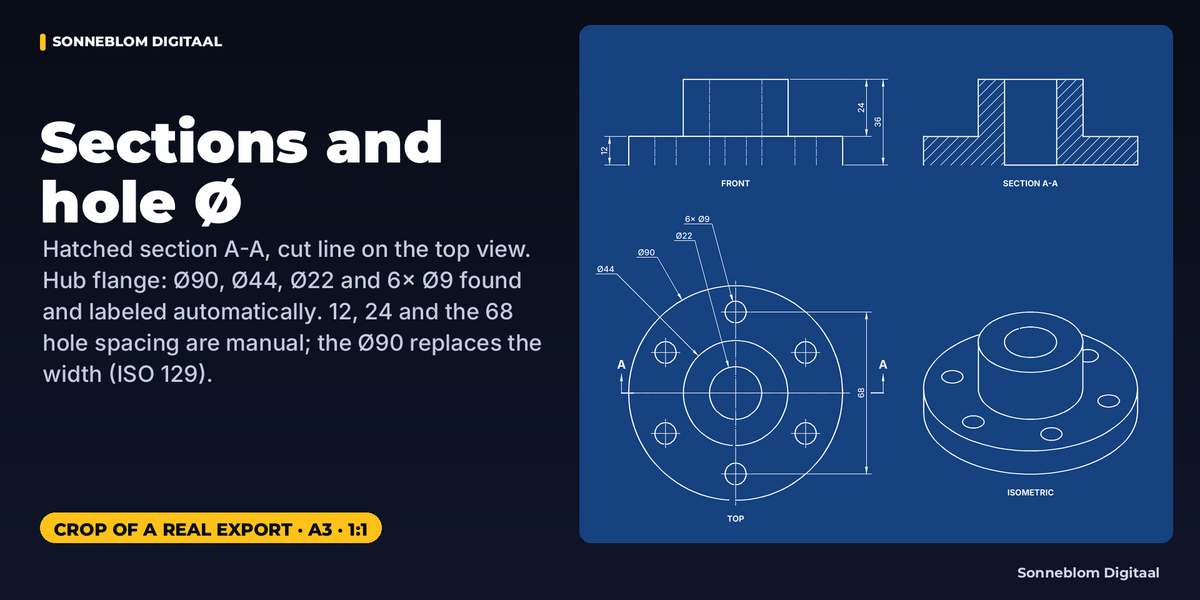
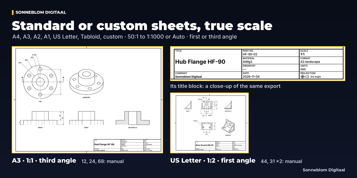
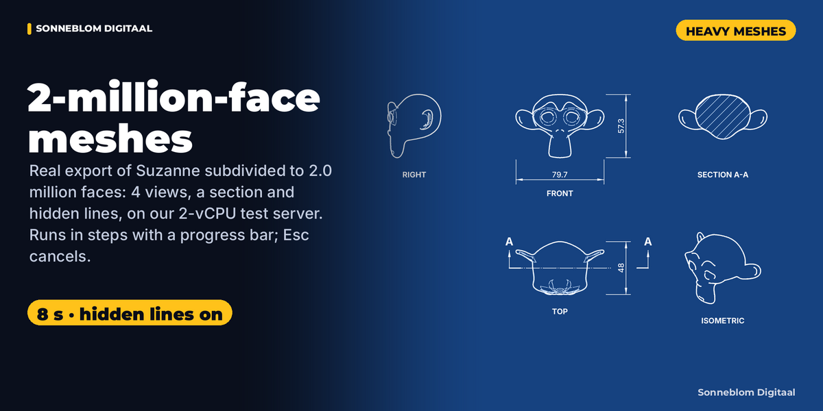
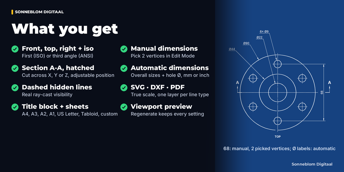
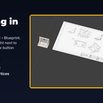
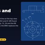
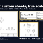
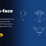
Blueprint Technical Drawings 1.0.0
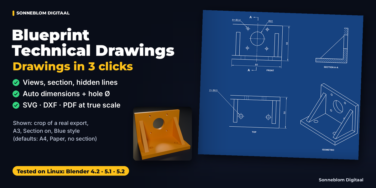
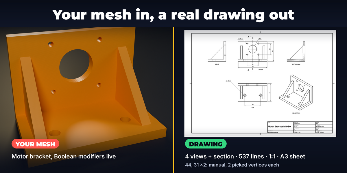
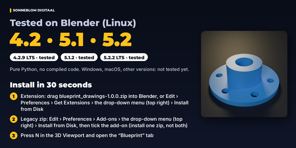
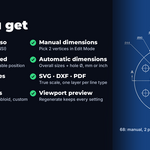
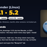
Dimensioned 2D technical drawings from your meshes: views, section, hidden lines, dimensions, title block; export SVG, DXF and PDF at true scale. Blender 4.2 LTS or newer, tested on 4.2 LTS, 5.1 and 5.2 LTS.
Install
-
Extension (Blender 4.2+): download
blueprint_drawings-1.0.0.zip, then Edit › Preferences › Get Extensions › the drop-down menu (top right) › Install from Disk, or drag the zip into Blender. -
Legacy add-on zip: install
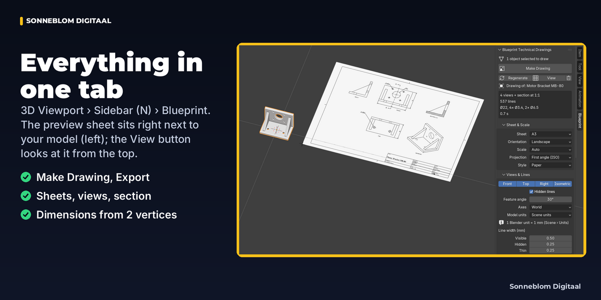
blueprint_drawings-1.0.0-legacy.zipvia Edit › Preferences › Add-ons › the drop-down menu (top right) › Install from Disk, then tick "Blueprint Technical Drawings". - Press N in the 3D Viewport and open the Blueprint tab.
Note: install one of the two zips, not both: a second copy registers nothing, says so in a popup and one console line, and Blender leaves it unticked.
Uninstall
Before you uninstall (recommended): in each .blend that used the add-on, click Remove Blueprint Data from This File (Blueprint tab › Help, or the add-on's Preferences) and save. It asks first and shows what goes.
- It deletes the preview sheets and their objects.
- It removes the Blueprint settings, manual dimensions and stored object lists from every scene of that file.
- Your own objects are not changed.
Then Edit › Preferences › Add-ons (or Get Extensions), find "Blueprint Technical Drawings", untick it and choose Uninstall / Remove. Every class, panel, handler and timer the add-on registered is removed.
What stays in files you did not clean:
- The Blueprint settings and manual dimensions, as scene data. A reinstall finds them again.
- The preview sheet objects (each with a small "blueprint_preview" tag, which copies of them keep), with the materials "Blueprint Paper" and "Blueprint Ink". Remove Preview deletes them while the add-on is installed.
- After an uninstall: in the Outliner, right-click the "Blueprint preview" collection › Delete Hierarchy. The sheet leaves the viewport; its objects and the two materials stay in the file, unseen (see One limit).
- To remove those too: install the add-on again, click Remove Blueprint Data from This File, save, then uninstall.
- The links to the objects you drew or dimensioned. They are normal Blender object links inside the scene's Blueprint data. The add-on never writes anything onto your objects.
- One limit: such a link counts as a user of the object or of the preview collection it points to.
- An object you delete after the uninstall stays in the file, unseen, while the link exists (the preview's objects too). Remove Blueprint Data before you uninstall avoids this.
- While the add-on is enabled it lets go of deleted objects and of a preview collection that is in no scene by itself: right after the delete, when a file is opened and when the add-on is enabled again.
Quick start
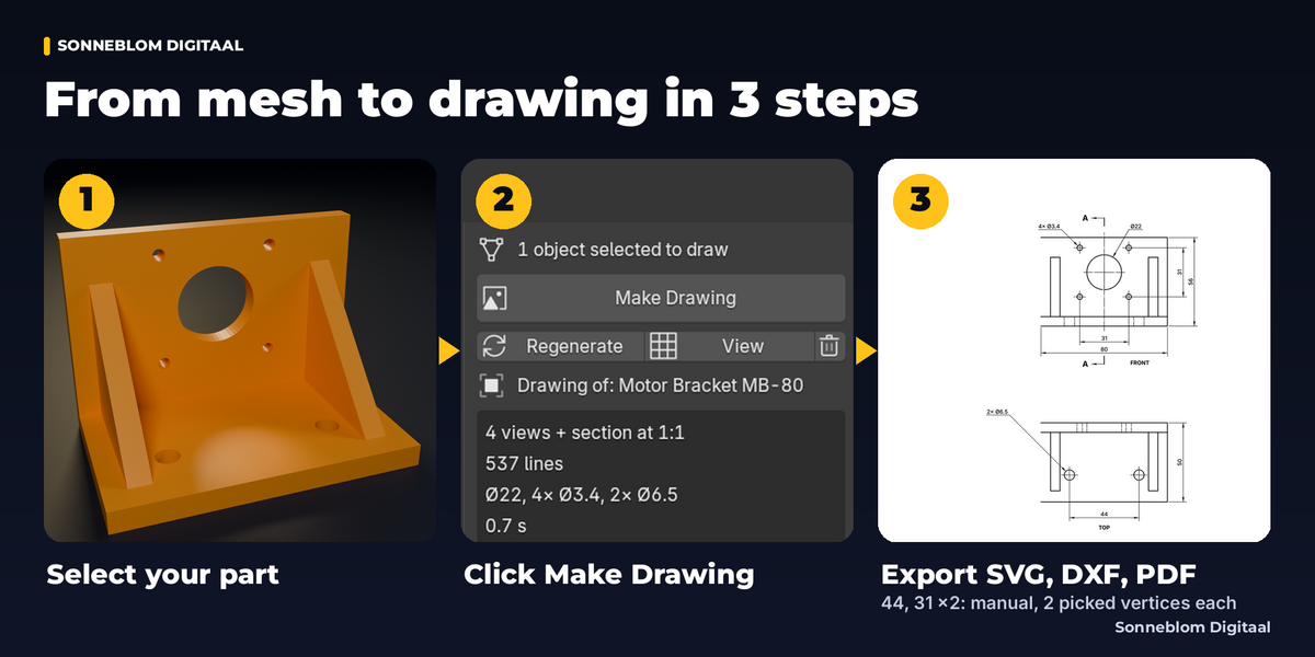
- Select your mesh object(s) (Object Mode; in Edit Mode the current edit mesh is drawn).
- Blueprint tab › Make Drawing. The preview sheet appears in the viewport, right of the model; View frames it from the top.
- Adjust Sheet & Scale, Views & Lines, Section, Dimensions, Title Block; click Regenerate.
- Export panel › Export. The report shows where the files went; the folder button opens it.
Panels and settings (defaults)
In a new scene only the main panel is shown: the sub-panels below appear after the first Make Drawing or a click on Edit Settings.
| Setting | Default | What it does |
|---|---|---|
| Settings line + Edit Settings | — | Shown in a scene that has no Blueprint settings yet (a new scene, a file from a colleague): the line lists what the first drawing will use (your Preference defaults). The sub-panels Sheet & Scale, Views & Lines, Section, Dimensions, Title Block and Export appear after the first Make Drawing or a click on Edit Settings; only then does the scene store add-on settings (a file opened with the tab visible and saved again stays free of add-on data) |
| Make Drawing | — | Draw the selected mesh objects and show the preview |
| Regenerate | — | Redraw the same objects with the current settings |
| View / Remove Preview | — | Look at the preview sheet from the top / delete the preview objects |
| Cancel (while working) | — | Stops a running drawing or export from another window (in the window that started it, press Esc: clicks outside the 3D Viewport are ignored there while it runs) |
| Sheet | A4 | A4, A3, A2, A1, US Letter, Tabloid, Custom |
| Orientation | Landscape | Landscape or portrait |
| Width / Height (mm) | 297 / 210 | Custom sheet size as typed, 148–5000 mm (Orientation is hidden for Custom) |
| Scale | Auto | Auto or 50:1, 20:1, 10:1, 5:1, 2:1, 1:1, 1:2, 1:5, 1:10, 1:20, 1:50, 1:100, 1:200, 1:500, 1:1000 |
| Projection | First angle (ISO) | First angle (ISO) or Third angle (ANSI) |
| Style | Paper | Paper (black on white) or Blue (white on blue) for SVG and PDF (the viewport preview always uses the Paper colors) |
| Front / Top / Right / Isometric | on | Which views are drawn |
| Hidden lines | on | Dashed hidden edges in front, top and right views |
| Feature angle | 30° | Edges whose faces meet at more than this angle are drawn (1°–179°); exactly this angle is not (a 12-segment cylinder, 30° between its faces, shows only its outline) |
| Axes | World | World axes, or the axes of the active object (for rotated parts) |
| Model units | Scene units | Scene units (Metric / Imperial: unit scale × 1 m; Unit System None: 1 unit = 1 mm), or 1 unit = 1 mm / 1 cm / 1 m / 1 inch. With Scene units, a part over 10 m or under 1 mm gets a note in the report suggesting the right setting |
| Line width (mm): Visible / Hidden / Thin | 0.5 / 0.25 / 0.25 mm | ISO 128 line group 0.5 (wide 0.5, narrow 0.25); 0.05–2 mm. Dashes follow ISO 128-20: hidden 12d dash / 3d gap, center 24d / 3d / 0.5d / 3d (d = line width); dashed lines have square-cut (butt) ends so the dash lengths stay exact |
| Section A-A | off | Adds the section view. On the parent view the thin chain line of the cut stops 3 mm past the outline; its ends (thick stroke, arrow, letter A) sit just beyond the dimensions. A view label in the way of the lower end moves aside, under the view and at least 5 mm (one letter height) clear of the cut line and the letter |
| Cut across | Y | Axis the cut plane is perpendicular to (X, Y, Z) |
| Offset (mm / in) | 0 | Distance of the cut plane from the center of the part (faces only: loose vertices do not count), in the dimension units (inch when Units = inch); switching Units converts it, so the plane stays put |
| Look from the other side | off | Keep the other half |
| Hatch spacing (mm) | 3 | Distance between hatch lines on the sheet (0.5–50); walls thinner than two spacings automatically get a closer spacing (about 2.5 lines across, at least 0.5 mm) |
| Overall dimensions | on | Width, height, depth |
| Hole diameters | on | Ø labels and center marks for round holes and cylinders (off: no hole search at all) |
| Repeat in every view | off | Also repeat dimensions another view already shows. Off (ISO 129): a size shown once is not repeated, and an overall size equal to a labeled outer Ø is left out (a Ø90 flange gets no "90" width on its Front view) |
| Units | mm | mm or inch (dimension text; DXF coordinates). Chosen here, not taken from Scene › Units: an Imperial scene still writes mm until you pick inch |
| Decimals | 1 | 0–4 (inch adds 2) |
| Trim zeros | on | 40 instead of 40.0 |
| Manual dimensions list | empty | + next to the list (Add Dimension: Edit Mode, 2 vertices): an aligned point-to-point dimension; view per dimension, − remove, X remove all |
| New dimension in view | Auto | View for the next dimension (Auto = where the points are furthest apart) |
| Title / Part no. / Material | empty | Drawing title; empty = the name of the active object if it is drawn, else of the first drawn object |
| Drawn by | — | Free text |
| Date | empty = today | YYYY-MM-DD |
| Company | empty | Shown in the title block |
| Folder | //drawings/ | Export folder; // = the .blend file's folder, so the default is a "drawings" folder next to the .blend (file not saved yet: home/Blueprint drawings/drawings) |
| File name | empty = title | Base name of the files |
| SVG / DXF / PDF | all on | Formats written by Export |
| Overwrite | on | Replace existing files; off = stop with a message before the drawing is made. File not saved yet and a relative folder (the shared home/Blueprint drawings): never overwrites, with Overwrite on or off; a second export gets " (2)" |
Preferences
Edit › Preferences › Add-ons › Blueprint Technical Drawings holds the defaults for new scenes: sheet, orientation, projection, style, units, decimals, company, drawn by, line widths, model units and export folder. A scene takes them when its first Make Drawing or Export finishes, or when you click Edit Settings; until then the panel says so. Opening, saving or editing a file, showing the Blueprint tab, an early error or Esc never write them into a scene. To apply them to a scene that already has settings, use Help › Load Preference Defaults. The Preferences also hold Max edges per view (200,000), the safety limit for very heavy meshes, and, like the Help panel, Remove Blueprint Data from This File (see Uninstall).
Layers (SVG groups, DXF layers, PDF layers)
| Layer | Contents | DXF color |
|---|---|---|
| BORDER | Sheet frame (at least 0.7 mm wide) with the ISO 5457 centering marks; the title block's outer frame and its two column lines | 7 (black / white) |
| VISIBLE | Visible outlines of every view (DXF: closed POLYLINEs for loops, CIRCLEs for holes seen whole) | 7 |
| HIDDEN | Dashed hidden lines | 5 (blue) |
| SECTION | Outline of the section view A-A only | 6 (magenta) |
| HATCH | Section hatching | 8 (gray) |
| CENTER | Center marks (four arms from each hole center, so the lines cross on long dashes), the thin chain line of the cutting plane, and the two center lines of the projection symbol. In the SVG and PDF each one starts and ends with a long dash | 1 (red) |
| CUTLINE | The thick end strokes of the cutting plane A-A (on the parent view) | 1 (red) |
| DIM | Dimensions (automatic and manual) with their extension lines, hole leaders, arrows, the viewing arrows of section A-A | 7 |
| TEXT | Title block text and its row lines (the title-block grid), view labels, the section letters A, the projection symbol (cone and circles; its center lines are on CENTER) | 7 |
The layer names are the usual CAD layer names (CENTER, HIDDEN as in AutoCAD's line types). All texts of the add-on use US spelling (center, color, gray, license), as Blender itself does.
Workflows
- 3D-print part for a customer: A4, Auto scale, first or third angle, Section on, material "PETG", export PDF.
- Laser / CNC plate: On a new scene, first click Edit Settings in the Blueprint panel; the settings panels then appear.
- Then: scale 1:1, units mm, turn off every view except the one you cut (usually Top), turn Section off, export DXF and use only its VISIBLE layer in your CAM software.
- The BORDER layer (the sheet frame with the ISO 5457 centering marks, at least 0.7 mm wide) and the title block are in the DXF and SVG too. Hide or delete BORDER, TEXT and DIM before cutting.
- Several parts in one drawing: select them all; neighboring parts get different hatch directions (45°, 135°, 60°, 150°, 30°, 120°, repeating).
- Rotated part: Axes › Active object, so front/top/right follow the part instead of the world.
- Imperial: Units › inch (dimensions with 3 decimals by default, DXF in inches); the sheet stays true scale.
How it works
For each view the add-on draws sharp edges (faces meeting at more than the feature angle), open boundaries and silhouettes. Visibility is tested with ray casts every sheet millimeter along each edge; where visibility changes the edge is split by bisection. Collinear pieces are merged and hidden lines lying under visible ones removed. For the files, lines are joined into polylines; line ends closer than 0.02 sheet mm are welded, so a closed outline is one closed path even on slightly uneven meshes. In the section view, edges behind the cut face (inside the material) are covered by it, as on a real section. Section outlines are oriented by the face normals and filled with the nonzero winding rule, so overlapping shells of one object are one solid (parts with flipped faces use even-odd). Holes are closed sharp edge loops of 12+ vertices that fit a circle within 1 %; a hole is labeled in a view only when ray casts just inside its rim are visible there.
Tips
- Hard-surface models: keep the feature angle at 30°. Bevels with only 2 segments (45° steps): raise it to 50° so the bevel facets are not drawn.
- Bevels with 3 or more segments (30° steps or less) already show only their outline.
- Stray lines on a flat face usually mean flipped normals: Mesh › Normals › Recalculate Outside. Lines along UV seams of an imported glTF / FBX / STL: Mesh › Clean Up › Merge by Distance.
- Print PDFs at 100 % / actual size. The PDF has one optional-content layer per line type (a viewer with a layers panel can hide them; we have not tested specific viewers).
- You can stay in Edit Mode: Make Drawing uses the current edit mesh. In Edit Mode, Ctrl+Z only steps back through mesh edits: leave Edit Mode before undoing a drawing or an added dimension.
- Low-poly holes are labeled from 12 segments up (also when the walls are sharper than the Feature angle). 6-, 8- and 10-sided pockets are treated as polygons, not holes.
- Laser / CNC: turn off every view except the one you cut (usually Top) and turn Section off, then export the DXF at 1:1 in mm and cut the VISIBLE layer only.
- Otherwise the VISIBLE layer holds the outlines of every view.
- The result box in the panel shows a short summary; the full message is in the Info editor (and the status bar).
Troubleshooting
| Message | What to do |
|---|---|
| Select at least one mesh object | Nothing (or no mesh) is selected. Select the part in Object Mode. Curves/text: Object › Convert › Mesh. |
| "…" has no faces | The object only has vertices/edges. Draw a mesh with faces. |
| "…" is an empty mesh (no vertices or faces) | All geometry of the mesh was deleted. Select another object, or undo the delete. |
| "…" has invalid vertex positions (NaN or infinite values …) | The mesh contains broken coordinates, usually from a damaged import. Repair or re-export the file in the program it came from and import it again. |
| "…" has an invalid (NaN or infinite) location, rotation or scale | Object › Clear › All Transforms (or type normal values in the N panel), then draw again. |
| The part is … long (Model units: Scene units …): set Model units to … | A note, not an error: the part is over 10 m or under 1 mm, which usually means the wrong unit (a millimeter STL in Blender's default meter scene). Set Views & Lines › Model units as suggested and Regenerate. If the size is right, set Model units to the unit you modeled in (the note names it, e.g. "1 unit = 1 m"): an explicit Model units setting never shows this note. |
| The selection has no size / has a zero scale on one axis | All vertices are at one point, or the object scale has a 0. Fix the scale (Ctrl+A › Scale). |
| Turn on at least one view | All views are switched off in Views & Lines. |
| The section plane … misses the part | The section offset is outside the part. Use an offset within the value shown. |
| The section plane cuts no faces | The plane passes through a gap (e.g. between two parts). Change the offset or axis. |
| Views do not fit the sheet at 1:1 (use 1:2 or a bigger sheet) | A fixed scale is too big for the sheet. Use the suggested scale, Auto, or a bigger sheet. |
| Noisy or scanned surface: … | Many edges are sharper than the feature angle (typical for scans). Raise Feature angle to 60–80° or turn Hidden lines off. |
| Heavy mesh: up to … edges per view left out | The per-view edge limit was reached. Softest feature edges go first; outlines are kept, and if silhouettes alone exceed the limit they are thinned evenly over the view (the note then says how many silhouette edges were left out, so the outline may have gaps). Raise Max edges per view in the Preferences if you need them all. |
| N edges have flipped neighbor faces | Some faces point inwards. Edit Mode › Mesh › Normals › Recalculate Outside. |
| Dimension N … its view is turned off / has zero length | Turn the view on, or pick another view for that dimension (the two points line up along the view direction). |
| Dimension …: a hole Ø leader crosses one of its extension lines | A note: on a crowded view no leader position avoided that manual dimension. Draw the dimension in another view (its View setting), pick other points, or turn Hole diameters off for this drawing. |
| … view: a hole Ø leader passes close to another hole | A note: the holes of that view are so close (at this scale) that no leader position keeps clear of every other hole and center mark; the drawing is made with the fewest crossings. Choose a larger scale or sheet, or turn off views you do not need. |
| … view: N hole diameters, Ø leaders on the 8 largest (at most 8 per view); not labeled: Ø… | A note: more than 8 different hole sizes in one view (a hole-size test plate). The 8 largest get a leader, so the drawing stays readable and the layout room stays small; the note lists the others. Label them with manual dimensions, or show those holes in another view. |
| … view: hole Ø leaders cross each other or a label | A note: the leaders of that view could not all be placed clear of each other. Choose a larger scale or sheet, or turn off views you do not need. |
| Could not remove the Blueprint data (…) | Remove Blueprint Data from This File failed: see the [Blueprint] line in the system console. Scenes linked from another file are never changed (the report names them): clean them in their own file. |
| Select exactly 2 vertices | The + button next to the Manual dimensions list (Add Dimension) needs exactly two selected vertices in Edit Mode. |
| … already exist: turn on Overwrite or change the file name | Overwrite is off and files with that name exist. |
| Cannot create the folder … / Cannot write to … / … is not a folder | The export folder is read-only or on a missing drive (typical: the default //drawings/ next to a .blend opened from a read-only place). Choose another folder in the Export panel (Folder), one you can write to; otherwise check the free disk space. Nothing was written and existing files were left as they were. |
| Cannot replace "…": it is open in another program | The file was there before and could not be replaced (permission denied): usually another program has it open. Close the file there and export again (or turn Overwrite off / change the file name). Existing files were left as they were. |
| Export failed (…) and the old file could not be put back: it is now ….blueprint_old | Rare: replacing a file failed, and so did putting the old one back (a file locked meanwhile, a drive removed). Your old file is not lost: rename it back by removing ".blueprint_old" from its name. The new files were taken out. |
| ….blueprint_old in … is the old file an earlier export could not put back | The export stops before writing anything, so that copy of your old file is never overwritten. Rename it back (remove ".blueprint_old") or move it away, then export again. |
| The file name is too long for this system | Most file systems allow 255 bytes per name (a Japanese or emoji character takes 3–4). Names are shortened to 200 bytes; a very long folder path can still be too long: choose a shorter file name or folder. |
| PDF: N characters printed as "?" (not in the PDF's standard font; the SVG keeps them, the DXF writes \U+ codes) | The PDF uses the standard Helvetica font, which covers Western European characters only. Use the SVG for Japanese, Cyrillic, Greek and other scripts: it keeps every character. The DXF writes them as \U+ codes (the DXF way to write such characters; we have not tested which CAD programs show them as characters). |
| "Name.svg" is a folder (or not a regular file) in … | A folder with the name of an export file is in the export folder. Export never renames or replaces it: rename that folder or change the File name. |
| Top view: N holes, center marks on 500 of them | A view shows more than 500 holes (perforated sheet, grille). The Ø labels count all of them and the DXF has every hole as a CIRCLE; only the center marks stop at 500 per view, so the drawing stays readable and fast. |
| The file path is too long (N characters with the temporary file name) | Folder plus file name, plus the temporary and backup names used while saving (up to 23 characters more), are longer than the system allows (Windows: 259). Choose a shorter folder or file name. |
| Canceled: nothing was changed | You pressed Esc (in the window that started the run) or the Cancel button while it was working. Nothing was created. |
| Canceled: the files were written; the viewport preview was left as it was | Export writes the files first and updates the preview last; you canceled during that last step. The files are complete; Regenerate updates the preview. |
| The viewport preview could not be updated (…); the files are fine | A note after Export: the files were written, the preview update failed. Click Regenerate; if it repeats, send us the [Blueprint] console line. |
| A drawing is being made: wait for it, press Esc in its window or click Cancel in the Blueprint panel | Another Make Drawing / Export is still running. Press Esc in the window that started it, or click Cancel in the Blueprint panel. |
| The scene changed while drawing (undo or file load) | Run it again. |
| Nothing to regenerate: select mesh objects and click Make Drawing | Regenerate redraws the objects of the last Make Drawing; they were deleted or none was made yet. Select the part and click Make Drawing. |
| Nothing to export: select mesh objects (or click Make Drawing first) | Export draws the objects of the last drawing, or the selection. Select the part. |
| Turn on SVG, DXF or PDF (Export panel, Export grayed out) | All three format toggles in the Export panel are off: tick at least one. |
| Section line not drawn: turn on the … view | The section line A-A is drawn on the Front, Top or Right view; all candidate views are off. Turn one on. |
| The 2 vertices are at the same place | The + button (Add Dimension) needs two vertices at different positions. |
| No dimension selected / Could not add the dimension | Click a dimension in the list first; for the second message see the [Blueprint] line in the system console. |
| No preview yet: click Make Drawing / Use this from a 3D Viewport | View needs a preview sheet and must be clicked in a 3D Viewport sidebar. |
| … does not exist yet: export first | Open Folder needs the export folder; it is created by the first Export. |
| … view: an extension line crosses a dimension line (…): two dimensions on one side that overlap only partly | Two dimensions on one side of a view where one starts inside the other and ends outside it: no order of the stack avoids a crossing. Measure both from one common point (nested), or pick one of them in another view. |
| … view: dimension … runs at an angle, so its extension lines cross other dimension lines | A diagonal manual dimension is placed beyond the dimensions along that side, but its extension lines start at the part and cross them. Pick two points level with each other (then it is stacked), or pick it in another view. |
| Could not remove the preview | Something prevented deleting a preview object; delete the Blueprint preview collection in the Outliner (the console line [Blueprint] says why). |
| Add-on preferences not found | The add-on is not enabled in Preferences; enable it and try again. |
| Installed twice: remove the legacy add-on or the extension (popup; the console line says "Add-on Blueprint Technical Drawings is already enabled from another install") | Both the extension and the legacy zip are installed; the second copy registered nothing and Blender leaves it unticked. Remove one in Preferences, restart Blender, enable the other. |
| "…" is disabled in the viewport or in an excluded collection: skipped | The object (a mesh or a collection-instance Empty) is not evaluated by Blender, so it cannot be drawn as you see it. Enable it (monitor icon / collection checkbox) and Regenerate. |
| 1 stored object no longer in the scene / N stored objects no longer in the scene | An object of the last drawing was deleted. Select what you want and click Make Drawing. |
| Skipped: … | One object of a multi-object selection has a problem (no faces, zero scale); the others are drawn. |
| "…" has no mesh data after its modifiers | Shown for an object with a Geometry Nodes modifier: the setup outputs instances (add a Realize Instances node before the Group Output) or nothing at all. |
| Section: 1 cut outline is open / Section: N cut outlines are open | The mesh is not watertight where the plane cuts it (single walls, planes, holes in the surface). The cut is outlined but not hatched; close the mesh or add a Solidify modifier. |
| Hole detection skipped: more than 400,000 sharp edges | Typical for scans (only with Hole diameters on). Raise the feature angle, or turn Hole diameters off; holes in such meshes can be dimensioned by hand. |
| Stopped: undo / redo during the drawing / a file was loaded / an object being drawn (or its view layer) was deleted / an object being drawn was changed during the drawing | Something changed the data while a drawing was being read (possibly a click in the header or in another window: a modifier toggled, an edit, a move, a deleted view layer). Nothing was changed; run it again. |
| The scene "…" is linked from another .blend file, so its settings are read-only | Make the drawing in the file that owns the scene, or make the scene local first. |
| N open edges lie on top of other open edges: split vertices … | The mesh has split vertices along UV seams or hard edges (glTF, FBX, some STL / 3MF exporters). Edit Mode › Mesh › Clean Up › Merge by Distance, then Regenerate. |
| Very long edges in total: visibility checked every … sheet mm | Above 20 million samples per view the sample spacing grows (memory limit). Use a smaller sheet / scale, or fewer views. |
| Dimension N (…): its object was deleted or is not in this scene: skipped | Remove that dimension from the list (or add it again). |
| N curve / text / other non-mesh objects in "…" skipped | An instanced collection contains curves or text: convert them to mesh to draw them. |
| "…" is in Sculpt Mode with Dyntopo | Dyntopo keeps its own copy of the mesh: leave Sculpt Mode, then Regenerate to draw the latest shape. |
| Exported the stored drawing of …, not your current selection | Export writes the objects of the last Make Drawing (shown at the top of the Export panel). To export the selected objects instead, click Make Drawing, then Export. |
| Could not open the file browser (…). The folder is … | Your system has no file manager Blender can start; open the folder shown yourself. |
| Could not load the preference defaults | See the [Blueprint] line in the system console; usually a linked scene. |
| Could not add the settings (…) | Edit Settings failed: see the [Blueprint] line in the system console; usually a linked scene (make it local first, or work in your own scene). |
| Blueprint could not finish (…) | An unexpected error; nothing was changed (or, if the message says so, only the viewport preview was updated). Send us the line starting with [Blueprint]: Windows: Window › Toggle System Console; macOS / Linux: start Blender from a terminal and repeat the step. Starting Blender with --debug (or the environment variable BLUEPRINT_DEBUG=1) adds the full traceback. |
| N loose vertices (not part of any face) ignored | Stray vertices or wire edges are not drawn and do not count for the size, scale or section. Mesh › Clean Up › Delete Loose removes them. |
| Section: overlapping shells in "…" are drawn as one solid | The object has shells that intersect (e.g. after Ctrl+J). The section is filled as their union and the inner outlines are left out. A Boolean Union or Mesh › Clean Up makes one clean shell. |
| Section: parts run into each other in the cut | Two selected objects interpenetrate. Each is hatched in its own direction, so the overlap shows crossed hatching. Check the model; parts that only touch give no note. |
| N Geometry Nodes instances in "…" skipped | The Geometry Nodes setup puts out instances, which are not drawn. Add a Realize Instances node before the Group Output. |
| Very many instances: only the first 5,000 are drawn | The selection instances more than 5,000 objects (scatter, particles). Draw a smaller selection, or make the instances real for the part you need. |
| "…" is in Edit Mode: … (not shown in Edit Mode) left out | In Edit Mode Blender does not evaluate modifiers whose Edit Mode display is off. Tab to Object Mode to draw them. |
| File not saved yet: written as "… (2)" | The .blend is not saved, so Export uses the shared home/Blueprint drawings folder and never overwrites a file there. Save the .blend first, or choose an output folder. |
| Very heavy mesh (question before it starts) | Above 3 million evaluated faces the add-on shows the expected time, pauses and memory and asks first (not again for Export right after drawing the same objects with the same settings, when nothing in them was edited or moved since: that reuses the drawing; any other change asks again). Instances of Verts / Faces / particle instancers are counted during the run, not in this estimate. Draw it, or Cancel and turn Hidden lines off, draw fewer objects or decimate a copy. Scripts (bpy.ops) are never asked. |
Limits
- Meshes only: convert curves and text to mesh first; Geometry Nodes instances need a Realize Instances node. Collection instances, Verts / Faces instancing and particle instances of meshes are drawn. Non-mesh selected objects are skipped and counted in the report.
- Dimensions: overall sizes and hole diameters are automatic; there are no automatic hole-position dimensions. Manual dimensions are aligned (point to point) between two vertices, so a hole center without a vertex cannot be picked.
- The title block has no revision, sheet-number or tolerance fields: add those in your CAD program.
- The isometric view shows visible lines only and has no dimensions; the section view shows no hidden lines (drafting convention).
- Hole labels only in front, top or right views looking along the hole axis and showing its rim. Polygons with fewer than 12 sides are never holes; a 12-gon pocket is taken for a round hole.
- A chamfered rim gives one Ø (the bore); a counterbore, a countersink, a stepped bore, a thin tube and holes in two stacked parts keep both diameters.
- Sections: overlapping shells of one object are filled as one solid (nonzero rule); for an object with flipped faces the even-odd rule is used, so there an overlap stays unhatched (Recalculate Outside fixes it).
- Two interpenetrating parts are each hatched (crossed hatching in the overlap) and the report says so.
- Instances: at most 5,000 per drawing (the report says when more were skipped); Geometry Nodes instances are not drawn (Realize Instances).
- While a drawing runs only viewport navigation passes: mouse wheel, middle mouse, numpad, Ctrl+Space, and left clicks inside the 3D Viewport itself (navigation gizmo, Alt+click navigation, selecting).
- Clicks on menus, the sidebar or other editors and all other keyboard shortcuts, Ctrl+S included, wait until it is done. Esc cancels in the window that started the run; from another window use the Cancel button in the Blueprint panel.
- One drawing (one sheet) per scene; use another scene for a second drawing.
- Split vertices: meshes from glTF / FBX / some STL exporters can have split vertices along UV seams. The seams are then drawn as lines and sections are not hatched.
- Mesh › Clean Up › Merge by Distance fixes it (the report says so).
- ISO 129: an overall size that equals a labeled outer Ø is not repeated, also not in another view (a Ø90 flange gets no "90" width in its Front view).
- Tick Dimensions › Repeat in every view to show it anyway.
- DXF units: R12 has no official units field. The file is in mm (or inch with Units = inch); the newer $INSUNITS header value is written too (we have not tested which CAD programs use it).
- Line widths are kept in SVG and PDF; the DXF uses fixed layer colors (see Layers).
- Very noisy scans give busy drawings: raise the Feature angle or turn Hidden lines off. A per-view edge limit (Preferences) keeps huge meshes safe.
- Many hole sizes: at most 8 diameters per view get a Ø leader (the 8 largest); the report names the others ("… view: N hole diameters, Ø leaders on the 8 largest").
- The leaders are planned only at the scale the layout chose, with a fixed amount of work per plan, in steps (Esc works).
- When no position keeps every leader clear, the drawing is made with the fewest crossings and the report says so.
- Many holes: at most 500 holes per view get a center mark (a perforated sheet, a speaker grille).
- The Ø labels still count every hole, the DXF has every hole as a CIRCLE, and the report says when the limit was reached.
- In Edit Mode, modifiers whose Edit Mode display is off are left out (as you see them); the report says so. Tab to Object Mode to draw them.
- File not saved yet: Export writes into the shared home/Blueprint drawings folder and never overwrites a file there, whatever the Overwrite setting: a second "Cube" becomes "Cube (2)". Save the .blend to export next to it.
- Chain lines end with a long dash in the SVG, the PDF and the preview.
- In the DXF the pattern comes from the CENTER line type (R12 has no per-line pattern scale), so it is not fitted to each line.
- DXF R12 only (no lineweights in DXF). PDF title-block text supports Western European characters only (standard Helvetica font, no embedded fonts): Japanese, Cyrillic, Greek and other scripts become "?" in the PDF, and the export report says how many.
- Use the SVG for other scripts; it keeps every character.
- Visibility is sampled every sheet millimeter: an occluder thinner than that can be missed. With a very large total edge length (over 20 million samples per view) the spacing grows and the report says so.
- Long steps: on a multi-million-face mesh the longest single steps (Blender reading the mesh with its modifiers, one view's visibility pass) pause the window.
- Each takes up to about 2.5 s at 1.57 million faces, longer on bigger meshes (no redraw, Esc is read right after). Above 3 million faces the add-on first shows an estimate (time, pauses, memory) and asks.
- Undo, a file load or deleting the part in another window stops a running drawing cleanly. Repeat Last (Shift+R) starts the same stepped run again (progress bar, Esc), with the heavy-mesh question again above 3 million faces.
- Repeat History and the Adjust Last Operation panel do the same: an earlier answer is never reused. Running the operators from a Python script (bpy.ops) runs them to the end at once.
- The preview lines are loose mesh edges: they show in Solid and Wireframe shading with Overlays on (Overlays off, Material Preview or Rendered: only the blank sheet shows).
- A heavy preview (hundreds of thousands of edges) is stored in the .blend and in every undo step: click Remove Preview before saving to keep the file small.
- Loose edges use the theme wire color, so the preview always uses the Paper colors (Style only changes the SVG / PDF).
- Hole leaders keep clear of the rims and center marks of the other holes, of each other and their labels, of the dimension on the right and of the extension lines of manual dimensions.
- On a very crowded view (many holes at a small scale) that can be impossible: the report then says so, and a larger scale or sheet gives them room.
- Other texts can still touch on crowded views: move them in an SVG editor or your CAD program.
- Scenes made with Scene › New › Linked Copy share the "Blueprint preview" collection: a drawing made in one replaces the preview in the other.
- The last drawing is kept in memory for a quick Export (drawings over 3 million lines are not kept); it is freed when you open another file.
- Manual dimensions store the vertex positions when added; if you edit the mesh later, delete and add the dimension again (moving the object is fine).
- The points are the Edit Mode vertices (before modifiers, active shape key): on Array, Mirror or Boolean results a picked point is not always on the drawn geometry.
- Pick vertices that the modifiers leave in place, or apply them on a copy. Manual dimensions go outside their view.
- On each side of a view the overall and the manual dimensions are stacked by length (ISO 129-1): the shortest closest to the view, the overall dimension outermost, so no extension line crosses a dimension line.
- The layout keeps room for them.
- Two dimensions that overlap only partly (one starts inside the other and ends outside it) cannot avoid a crossing in one stack: the report says so (measure both from one common point, or pick one in another view).
- A dimension too short for its arrows between the extension lines has them outside; where an outside arrow would cross a neighbor's extension line, that end gets a dot instead (ISO 129-1).
- With dots at both ends the dimension has no tail, and its value stays over its middle (the outer extension lines leave a gap there).
- A diagonal dimension (two points not level with each other) is placed beyond the stack of its side, and the layout keeps room for it. Its extension lines can still cross other dimension lines: the report then says so.
- As in ISO 129-1, each extension line starts 1 mm from the point it measures (it may cross the outline) and is left open where it would run through a text.
- To dimension hole positions, pick the same rim point of two holes (e.g. both rightmost points) or a rim point on a hole's center line: the dimension is then drawn between the hole center lines, which are extended to it.
- Hole leaders are placed clear of these extension lines; when that is impossible the report says so.
FAQ
Is the PDF / SVG / DXF really at true scale?
Yes. The sheet is written in millimeters (SVG user units = mm, PDF page in points at 72 per inch, DXF in mm or inch). At 1:1 a 100 mm edge is 100 mm: 283.46 pt in the PDF. Print the PDF at 100 % / actual size, not 'fit to page'.
Does it use my modifiers?
Yes. It draws the evaluated mesh, as you see it in the viewport: Booleans, arrays, mirror, bevel, subdivision (in Edit Mode, modifiers hidden in Edit Mode are left out, with a note). Your mesh is never changed.
Can I use the DXF for laser cutting or CNC?
Yes. Set Scale to 1:1, units mm, turn off every view except the one you cut (usually Top) and turn Section off; otherwise the VISIBLE layer holds the outlines of every view. In your CAM program use the VISIBLE layer only and hide all others (BORDER, HIDDEN, SECTION, HATCH, CENTER, CUTLINE, DIM, TEXT). Outlines are joined, closed POLYLINEs (line ends closer than 0.02 mm are welded, so slightly uneven meshes from Booleans or STL files still give closed loops), and holes seen whole in that view are true CIRCLE entities (with Hole diameters on). Other curves (arcs, rounded corners, a hole partly hidden) are short straight segments, as fine as your mesh: use enough segments on curved edges, or fit arcs in your CAM program if it offers that. The file is plain DXF R12 (the plain ASCII format); our tests parse it back and check every entity, but we have not tested it in CAM programs, so try a small part first. On a new scene, first click Edit Settings in the Blueprint panel; the settings panels then appear.
Why are my hole diameters not labeled?
A hole is recognized when its rim is a closed loop of edges sharper than the Feature angle that forms a circle with at least 12 segments, and it is labeled in the view that looks along its axis and shows its rim (a vertical hole in the Top view). A single chamfer is fine (you get the bore Ø). A rounded rim (a multi-segment bevel or a fillet) has no edge sharper than the feature angle: lower the Feature angle below the angle between the fillet facets, or add a manual dimension. Shade Smooth and Mark Sharp do not matter. Holes at an angle to all three views are drawn but not labeled.
My model is an STL in millimeters but the numbers are 1000× too big or small.
Set Views & Lines › Model units to '1 unit = 1 mm'. On a new scene, first click Edit Settings in the Blueprint panel; the settings panels then appear. Scene units follows Scene › Units (Blender's default scene counts 1 unit as 1 meter); when a part comes out over 10 m or under 1 mm, the report suggests the right setting (if the size is right, set Model units explicitly, e.g. '1 unit = 1 m', and the note goes away).
How fast is it on heavy meshes?
About 12–17 seconds for our 1.57-million-face test mesh with 4 views, a section and hidden lines; the longest single pause of the window is up to about 2.5 s, and Blender peaked at about 1.6 GB of memory. It runs in steps with a progress bar: you can orbit, pan and zoom (mouse wheel, middle mouse, numpad, the navigation gizmo) and Esc in the window that started it (from another window: the Cancel button in the Blueprint panel) cancels: Make Drawing leaves nothing behind; Export canceled after its files were saved keeps the files it wrote. Time, pauses and memory grow with the face count: above 3 million faces the add-on shows an estimate and asks first. On very big scans turn Hidden lines off or decimate a copy.
Can the PDF show Japanese, Cyrillic or Greek text?
Not yet: PDF title-block text supports Western European characters only (the PDF uses the standard Helvetica font, without embedded fonts), so other scripts show as "?" in the PDF and the export report says how many. Use the SVG for other scripts: it keeps every character (UTF-8 text, checked by our tests). The DXF writes them as \U+ codes (the DXF way to write characters outside its code page; emoji, outside that range, become ?). We have not tested which CAD programs show these codes as characters.
First angle or third angle?
First angle (ISO, Europe and most of the world) puts the top view below the front view; third angle (ANSI, USA) puts it above. Pick it in Sheet & Scale, set your default in the Preferences. The title block shows the matching symbol.
Can I edit the drawing afterwards?
Yes: the files are plain vector drawings. The SVG has one group per line type, marked as a layer the way Inkscape stores layers (inkscape:groupmode="layer"); the DXF has one layer per line type, the PDF one optional-content layer per line type. Our tests check these groups and layers in the files; we have not tested how each program shows them. Changes in Blender? Click Regenerate and export again; all settings are kept.
Changelog
1.0.0 (2026-11-04): initial release (see the feature list above).
License
GPL-3.0-or-later. © 2026 Sonneblom Digitaal.
Have questions about this product?
Login to message
| Blender Extension Compatible | Yes |
| Published | 3 days ago |
| Blender Version | 4.2 - 5.2 |
| Extension Type | Add-on |
| License | GPL |
Discover more products like this
blueprint Technical drawing dxf dimensions SVG orthographic PDF 3d printing