Blueprint Technical Drawings – 2D Views to SVG, DXF & PDF
 Sonneblom Digitaal
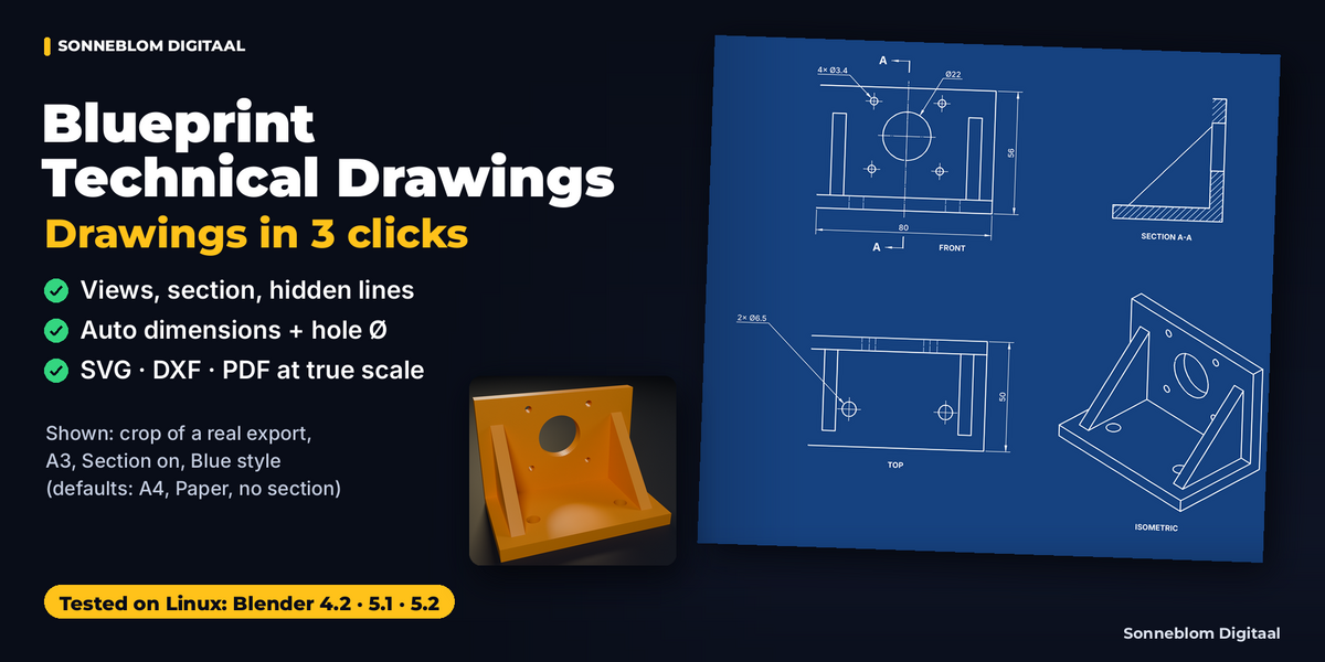
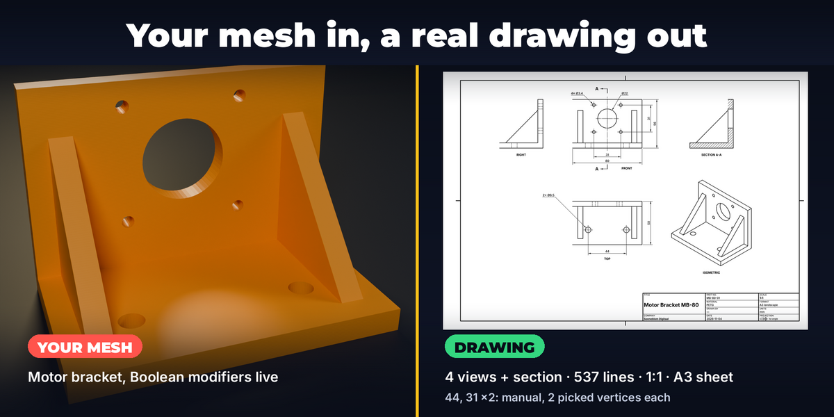
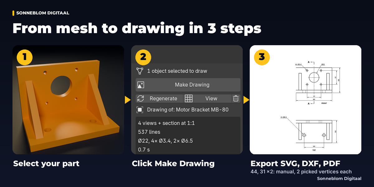
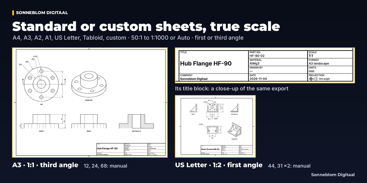

Yes. The sheet is written in millimeters (SVG user units = mm, PDF page in points at 72 per inch, DXF in mm or inch). At 1:1 a 100 mm edge is 100 mm: 283.46 pt in the PDF. Print the PDF at 100 % / actual size, not 'fit to page'.
Yes. It draws the evaluated mesh, as you see it in the viewport: Booleans, arrays, mirror, bevel, subdivision (in Edit Mode, modifiers hidden in Edit Mode are left out, with a note). Your mesh is never changed.
Yes. Set Scale to 1:1, units mm, turn off every view except the one you cut (usually Top) and turn Section off; otherwise the VISIBLE layer holds the outlines of every view. In your CAM program use the VISIBLE layer only and hide all others (BORDER, HIDDEN, SECTION, HATCH, CENTER, CUTLINE, DIM, TEXT). Outlines are joined, closed POLYLINEs (line ends closer than 0.02 mm are welded, so slightly uneven meshes from Booleans or STL files still give closed loops), and holes seen whole in that view are true CIRCLE entities (with Hole diameters on). Other curves (arcs, rounded corners, a hole partly hidden) are short straight segments, as fine as your mesh: use enough segments on curved edges, or fit arcs in your CAM program if it offers that. The file is plain DXF R12 (the plain ASCII format); our tests parse it back and check every entity, but we have not tested it in CAM programs, so try a small part first. On a new scene, first click Edit Settings in the Blueprint panel; the settings panels then appear.
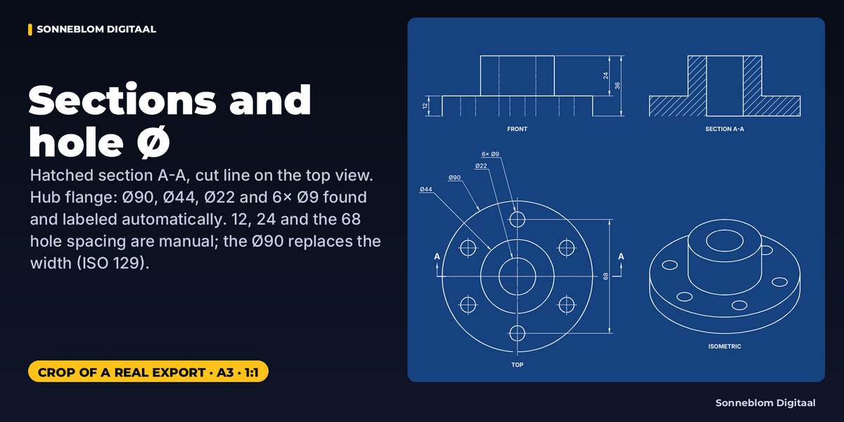
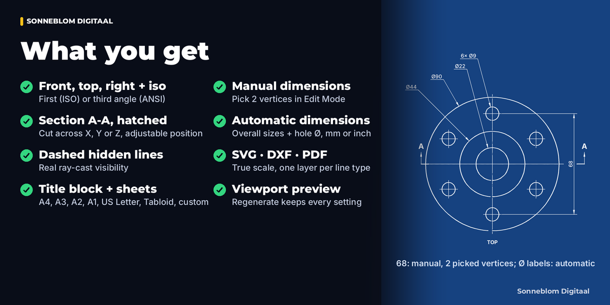
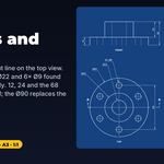
A hole is recognized when its rim is a closed loop of edges sharper than the Feature angle that forms a circle with at least 12 segments, and it is labeled in the view that looks along its axis and shows its rim (a vertical hole in the Top view). A single chamfer is fine (you get the bore Ø). A rounded rim (a multi-segment bevel or a fillet) has no edge sharper than the feature angle: lower the Feature angle below the angle between the fillet facets, or add a manual dimension. Shade Smooth and Mark Sharp do not matter. Holes at an angle to all three views are drawn but not labeled.
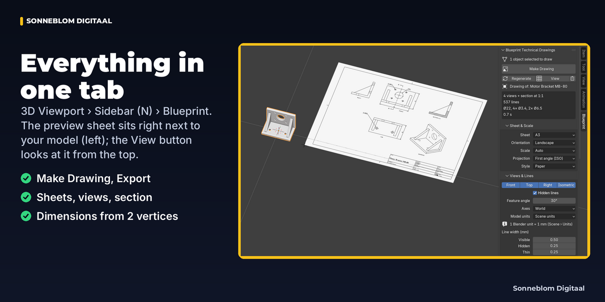
Set Views & Lines › Model units to '1 unit = 1 mm'. On a new scene, first click Edit Settings in the Blueprint panel; the settings panels then appear. Scene units follows Scene › Units (Blender's default scene counts 1 unit as 1 meter); when a part comes out over 10 m or under 1 mm, the report suggests the right setting.
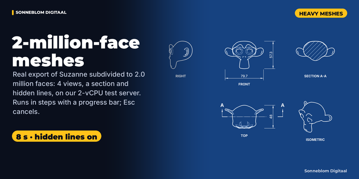
About 12–17 seconds for our 1.57-million-face test mesh with 4 views, a section and hidden lines; the longest single pause of the window is up to about 2.5 s, and Blender peaked at about 1.6 GB of memory. It runs in steps with a progress bar: you can orbit, pan and zoom (mouse wheel, middle mouse, numpad, the navigation gizmo) and Esc in the window that started it (from another window: the Cancel button in the Blueprint panel) cancels: Make Drawing leaves nothing behind; Export canceled after its files were saved keeps the files it wrote. Time, pauses and memory grow with the face count: above 3 million faces the add-on shows an estimate and asks first. On very big scans turn Hidden lines off or decimate a copy.
Not yet: PDF title-block text supports Western European characters only (the PDF uses the standard Helvetica font, without embedded fonts), so other scripts show as "?" in the PDF and the export report says how many. Use the SVG for other scripts: it keeps every character (UTF-8 text, checked by our tests). The DXF writes them as \U+ codes (the DXF way to write characters outside its code page; emoji, outside that range, become ?). We have not tested which CAD programs show these codes as characters.
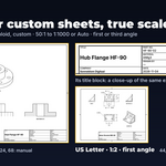
First angle (ISO, Europe and most of the world) puts the top view below the front view; third angle (ANSI, USA) puts it above. Pick it in Sheet & Scale, set your default in the Preferences. The title block shows the matching symbol.
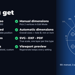
Yes: the files are plain vector drawings. The SVG has one group per line type, marked as a layer the way Inkscape stores layers (inkscape:groupmode="layer"); the DXF has one layer per line type, the PDF one optional-content layer per line type. Our tests check these groups and layers in the files; we have not tested how each program shows them. Changes in Blender? Click Regenerate and export again; all settings are kept.
Have questions about this product?
Login to message
| Blender Extension Compatible | Yes |
| Published | 3 days ago |
| Blender Version | 4.2 - 5.2 |
| Extension Type | Add-on |
| License | GPL |
Discover more products like this
dimensions 3d printing blueprint Technical drawing dxf SVG orthographic PDF