Drawing View — Architectural Drawings For Blender
 Arch on Arch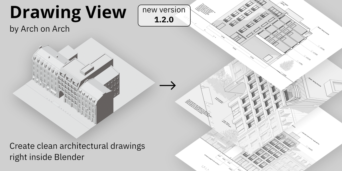
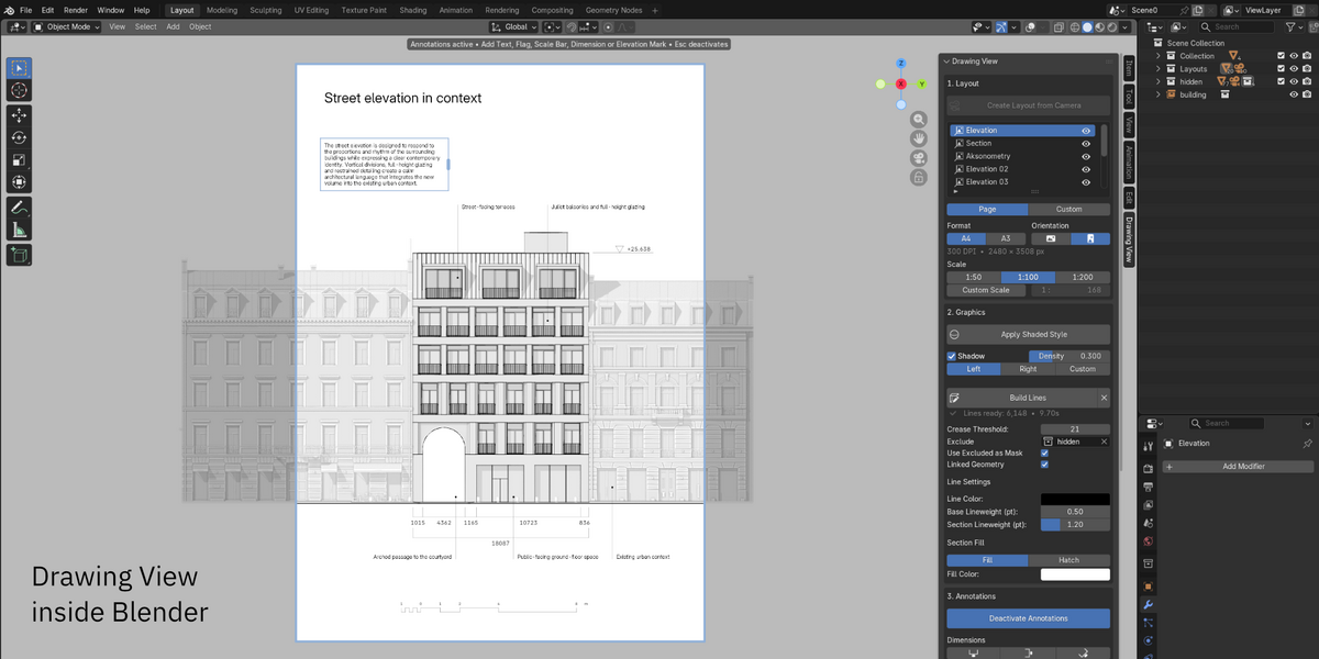

Drawing View — User Guide
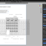
Drawing View is a Blender add-on for creating clean architectural drawings at real scale directly inside Blender.
The workflow is built around four main stages:
Layout → Graphics → Annotations → Export
A regular Blender camera becomes a Drawing View Layout with its own page and drawing scale. From there you can build architectural linework, add 2D drawing information, and export the finished Layout as PNG or PDF.
1. Installation and Updating
1.1. Installation
- Download the Drawing View ZIP file.
- Drag the ZIP file into the Blender window and confirm the installation.
- Open the Drawing View tab in the 3D View Sidebar.
Drawing View works locally inside Blender. An internet connection is not required for its core functionality.
1.2. Updating
If Superhive is connected to Blender as a Remote Repository, available Drawing View updates can be installed through Blender.
You can also update from a downloaded package. Open Drawing View's add-on preferences, click Update from ZIP..., and select a Drawing View ZIP file from a source you trust.
Project data is stored in the .blend file. If an update changes the saved line data used by an existing Layout, Drawing View will indicate that the linework needs to be rebuilt.
2. Quick Start
A typical Drawing View workflow looks like this:
- Create or select a Blender camera.
- Click Create Layout from Camera.
- Choose the page format and drawing scale.
- Position the Layout and refine the composition.
- Apply Shaded Style if you want a shaded base behind the linework.
- Click Build Lines.
- Click Activate Annotations.
- Add dimensions, elevation marks, scale bars, text, flags or callouts.
- Export the finished Layout as PNG or PDF.
You can create several independent Layouts in the same .blend file for elevations, sections, plans, axonometric drawings and other presentation views.
3. Layout
3.1. Creating a Layout
Select a Blender camera and click Create Layout from Camera.
The selected camera becomes a Drawing View Layout. A new Layout starts as an A4 Landscape, 1:100 orthographic drawing view aligned to the nearest world axis.
The camera is converted into the camera used by that Layout. If you want to preserve the original camera separately, duplicate it before creating the Layout.
Each Layout keeps its own page size, drawing scale, view, shading state, source-filter settings and annotations, so different drawings in the same project can be configured independently.
3.2. Layout List
Drawing View Layouts in the current Scene appear in the Layout list.
- Click a Layout row to activate and open it.
- Edit the Layout name directly in the list.
- Use the eye icon to show or hide its frame and direction markers in the normal 3D View.
The eye icon controls only the Layout helper visible in the 3D View. It does not disable the Layout or remove its drawing content.
3.3. Page Size
Drawing View provides two size modes:
- Page — A4 or A3 in Landscape or Portrait orientation.
- Custom — a custom rectangular Layout defined in millimetres or pixels.
Millimetre and pixel values describe the same physical Layout at a fixed 300 DPI. The resulting output resolution is shown directly in the Layout section.
Page mode, orientation and Custom dimensions belong to the active Layout and can therefore be different for every drawing.
Very large Custom layouts can require substantial memory. Drawing View displays a warning when the requested output becomes unusually large.
3.4. Drawing Scale
Drawing View uses real architectural drawing scales for orthographic Layouts.
Preset buttons are provided for:
- 1:50;
- 1:100;
- 1:200.
Enable Custom Scale to enter another scale denominator.
The selected scale belongs to the active Layout. It determines how much model space is represented on the physical sheet, while lineweights, text sizes and annotation graphics remain defined in paper-space units.
If the page, orientation or drawing scale changes the Layout projection, run Build Lines again to update the drawing.
3.5. Positioning and Composition
The selectable Layout frame represents the drawing view in model space. Use normal Blender transforms and camera-view navigation to position it and refine the composition.
For a section drawing, the Layout plane also defines the cut position. Move the Layout through the model to the required section location and then run Build Lines.
3.6. Duplicating Layouts
Use Shift+D to duplicate a selected Layout. The duplicate becomes a new independent Layout and immediately enters Blender's normal move interaction.
The new Layout inherits the source Layout's page, scale and configuration, but starts as a new drawing. Generated linework and placed annotations are not copied.
When a completely new Layout is created from another camera, the current Layout's Exclude, Use Excluded as Mask and Linked Geometry choices are used as starting values. After creation, the new Layout keeps its own independent values.
Alt+D linked duplication is not supported for Drawing View Layouts because every Layout is intended to remain an independent drawing entity.
3.7. Hiding and Deleting Layouts
Drawing View follows normal Blender interaction where practical.
- H hides selected Layouts.
- X or Delete deletes selected Layouts with confirmation.
4. Graphics
4.1. Shaded Style
Apply Shaded Style applies a predefined Solid viewport appearance intended as a clean architectural base for Drawing View linework.
The shaded base is optional. You can use linework by itself or combine it with the shaded representation.
After Shaded Style has been applied, you can control:
- Shadow — turn the architectural shadow on or off;
- Density — adjust shadow strength;
- Direction — Left, Right or Custom;
- Azimuth and Elevation for a Custom shadow direction;
- Shading Tint;
- Background Color.
These appearance settings are kept with the active Layout, so different Layouts can use different presentation states.
You can also adjust Blender's Solid Shading controls manually. Applying Shaded Style again restores the Drawing View preset for the active Layout.
4.2. Build Lines
Click Build Lines while viewing the active Layout to generate its architectural linework.
Drawing View distinguishes several drawing categories:
- Silhouette;
- Boundary;
- Crease;
- Intersection;
- Section.
The status below the Build button indicates whether the drawing is ready, needs rebuilding, has been cleared, or is currently being generated.
When model geometry, object positions, the Layout projection or another relevant Build setting changes, Drawing View can show Lines need rebuild. The existing completed drawing remains visible where possible until a new Build is ready.
Use the clear button next to Build Lines to remove the generated linework from the active Layout.
4.3. Crease Threshold
Crease Threshold controls the minimum fold angle displayed as a Crease line.
After Build Lines has been completed, changing the threshold updates the visible Crease result directly without running the full Build again.
The Crease Threshold is shared by Drawing View Layouts in the current Blender Scene, providing a consistent crease definition across the project.
4.4. Exclude
Exclude allows you to choose a collection whose mesh objects should not generate Drawing View linework.
Meshes in child collections are excluded as well.
This is useful for:
- helper geometry;
- vegetation;
- high-detail context;
- objects that should remain visible only in the shaded representation.
Each Layout keeps its own Exclude collection, allowing the same Blender Scene to be represented differently in different drawings.
4.5. Use Excluded as Mask
When Use Excluded as Mask is enabled, excluded geometry does not create Drawing View lines, intersections, Section graphics or model snap anchors, but its visible surfaces can still hide drawing lines behind them.
Disable the option when excluded geometry should be ignored completely by Drawing View.
This choice belongs to the active Layout. Changing it requires Build Lines again.
4.6. Linked Geometry
Enable Linked Geometry when the active Layout should include read-only mesh geometry linked from external .blend files, including linked collection instances.
Linked geometry can participate in normal linework, visibility, intersections and Section graphics.
The Layout's Exclude collection still takes priority, so linked geometry contained in an excluded collection remains excluded.
Linked Geometry is enabled independently for each Layout. Changing it requires Build Lines again.
4.7. Line Settings
Line Settings become available after the first successful Build Lines in the project.
They control the common graphic appearance of Drawing View linework:
- Line Color;
- Base Lineweight;
- Section Lineweight;
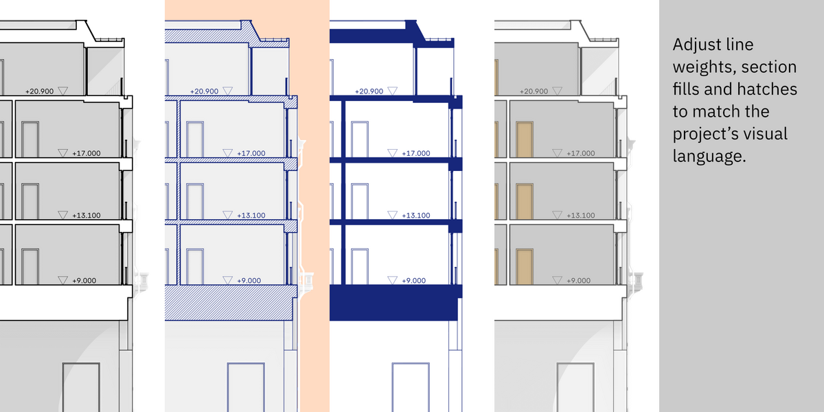
- Section Style — Fill or Hatch;
- Fill Color;
- Hatch Lineweight;
- Hatch Spacing.
These settings are shared by Drawing View Layouts in the current Blender Scene so that the project maintains one consistent line hierarchy.
Lineweights are defined in typographic points (pt) as physical paper-space values and do not change with viewport zoom.
Annotations use the same Line Color by default. A separate annotation color can be enabled later in Annotation Global Settings.
4.8. Sections
Section graphics are generated where model geometry crosses the active Layout plane.
To create a section:
- Position the Layout plane at the required cut.
- Run Build Lines.
- Adjust Section Lineweight and Section Style in Line Settings.
Fill produces a solid material fill. Hatch produces diagonal vector hatching on a white Section background.
Section appearance uses the shared Line Settings, so changes to Section lineweight, fill or hatch styling affect Drawing View Layouts in the current Scene.
4.9. Intersections
Intersection lines are calculated between separate objects or separate participating mesh structures.
Self-intersections within a single mesh are not calculated.
If an intersection is required between logically separate parts of one complex mesh, split those parts into separate objects where appropriate.
4.10. Large Scenes
Build time depends on the amount and complexity of geometry participating in the drawing.
Drawing View can display a warning before processing an unusually large scene. If Build Lines is slower than expected, hide or exclude geometry that does not need to participate in the final drawing, such as helper objects, dense vegetation or distant high-detail context.
The option to suppress Large Scene warnings lasts only for the current Blender session.
5. Annotations
5.1. Annotation Workspace
Drawing View includes a dedicated 2D Annotation layer for information that belongs to the architectural drawing rather than to the 3D model.
Annotations are stored with the Layout and exported together with it. They do not become Blender mesh geometry.
Enter the active Layout view and click Activate Annotations before creating or editing annotations.
Use Esc or Deactivate Annotations to leave the Annotation workspace and return to normal Layout navigation.
5.2. Tool Availability
Measured annotation tools are available only where their projected values are unambiguous.
- Plan Layouts support Dimensions and Scale Bars. Elevation Marks are not available.
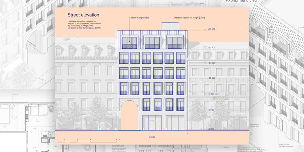
- Vertical elevation and section Layouts support Dimensions, Elevation Marks and Scale Bars.
- Tilted and axonometric Layouts support Text, Header, Flag and Callout, while Dimensions, Elevation Marks and Scale Bars are disabled.
Drawing View uses orthographic Layouts for scaled architectural drawings. Perspective drawing Layouts are not part of the current Drawing View workflow.
5.3. Snapping
Dimensions and Elevation Marks use model snap anchors prepared by Build Lines.
If one of these tools reports that model snap anchors are unavailable, run Build Lines for the active Layout.
Text, Header, Flag and Callout are free paper-space annotations and do not require model geometry to be created.
Free annotations use alignment guides while they are moved. Callout leader editing also uses soft orthogonal snapping. Hold Ctrl while moving a Callout anchor or knee to temporarily disable that orthogonal snap.
5.4. Selecting and Editing Annotations
With Annotations active:
- Click an annotation to select it.
- Shift-click adds or removes annotations from the current selection.
- Drag across empty sheet space to create a box selection.
- Hold Shift while box-selecting to add to the current selection.
- G moves the selected annotation using Blender-style interaction.
- X, Delete or Backspace deletes the selected annotation or selection.
- Ctrl+Z and Ctrl+Shift+Z undo and redo Annotation operations.
Text, Header, Flag, Callout and Scale Bar are free paper-space elements. Dimensions and Elevation Marks retain movement behaviour appropriate to their measured relationship with the model.
5.5. Dimensions
Drawing View provides two Dimension tools:
- Orthogonal Dimension — creates a horizontal or vertical dimension. The direction in which you move the dimension shelf determines its orientation.
- Aligned Dimension — follows the projected direction between the measured model points.
Dimensions require model snap anchors from Build Lines and are available in plan and vertical Layouts.
Orthogonal Dimension
- Choose Orthogonal Dimension.
- Click the first model point.
- Click the second model point.
- Move perpendicular to the measured points. Drawing View resolves the dimension as Horizontal or Vertical from the shelf direction.
- Click to place the shelf.
Additional model points can be added to the chain before placement.
Press X or Y during creation when you want to explicitly lock the current Orthogonal Dimension to the corresponding axis.
After the dimension has been placed, the tool remains active. Click another model point to begin the next dimension without restarting the tool, or press Esc to finish.
Aligned Dimension
- Choose Aligned Dimension.
- Click the first model point.
- Click the second model point.
- Move the dimension shelf to the required offset and click to place it.
Aligned Dimensions follow the projected direction between their model anchors instead of resolving to Horizontal or Vertical.
The tool remains active after placement so another dimension can be started immediately.
Dimension Chains
A selected Dimension chain provides controls for adding further model anchors or removing individual internal points from an existing chain.
This allows the chain to be refined later without recreating it.
Dimension Settings
When a Dimension is selected, the following controls appear:
- Dimension Style — Minimal, Architectural Tick or Open Arrow;
- Extension — Compact Extension or Full Extension;
- Units — mm, cm or m;
- Rounding — available values depend on the selected unit;
- Show Units — adds the selected unit suffix to dimension values.
Although these controls are shown while a Dimension is selected, they define the common Dimension presentation for the current Blender Scene. Changing them affects all Drawing View Dimensions in that Scene.
Dimension labels use the default Font Family and Font Weight defined in Annotation Global Settings.
5.6. Elevation Marks
Elevation Marks display the world-Z elevation of model points in vertical elevation or section Layouts.
They require model snap anchors from Build Lines.
- Choose Elevation Marks.
- Click a model point.
- Move horizontally to position the mark.
- Click to place it.
The tool remains active after each mark is placed, allowing multiple elevations to be added consecutively until you press Esc.
When an Elevation Mark is selected, you can adjust:
- Elevation Style — Compact or Extended;
- Units — m or mm;
- Rounding.
These controls define the common Elevation Mark presentation for the current Blender Scene, so changing them affects all Drawing View Elevation Marks in that Scene.
Elevation labels use the default Font Family and Font Weight from Annotation Global Settings.
5.7. Scale Bars
Scale Bar adds a graphical scale reference linked to the active Layout's drawing scale.
Scale Bars are free paper-space annotations and can be moved independently on the sheet.
Up to ten Scale Bars can be placed on one Layout.
At architectural scales up to 1:2000, a selected Scale Bar can use one of three styles:
- Architectural;
- Graphic;
- Classical.
For scales above 1:2000, Drawing View automatically uses a compact Cartographic scale-bar configuration.
The selected style belongs to that Scale Bar, so several Scale Bars on the same Layout can use different styles.
Scale Bar labels use the default Font Family and Font Weight from Annotation Global Settings.
5.8. Text
Text creates a regular paper-space text block.
Choose the Text tool, move the block to the required position and click to place it.
Text supports multiple lines and automatic wrapping inside a resizable text box.
Double-click an existing Text block to edit its content directly on the Layout.
5.9. Header
Header creates a larger text preset at the standard top-left position of the Layout. After creation, a Header behaves as an editable Text block and supports the same typography, formatting and inline editing controls.
5.10. Inline Text Editing
Double-click a Text, Header, Flag or Callout to edit its text directly on the Layout.
While the inline editor is active:
- click and drag to select text;
- double-click to select a word;
- triple-click to select a paragraph;
- Enter inserts a new line;
- Ctrl+Enter applies the edit;
- Esc cancels the current edit;
- Ctrl+A selects all text;
- Ctrl+C, Ctrl+X and Ctrl+V provide standard copy, cut and paste;
- Ctrl+Shift+V pastes text without its formatting;
- Ctrl+B, Ctrl+I and Ctrl+U apply Bold, Italic and Underline;
- Ctrl+Z and Ctrl+Shift+Z provide Undo and Redo inside the current text-editing session.
The text-box width handle remains available while editing, so wrapping can be adjusted without leaving the inline editor.
5.11. Text Formatting
When Text, Header, Flag or Callout is selected, its typography can be adjusted directly from the Annotation panel.
Available controls include:
- Font Family;
- Weight;
- Bold, Italic and Underline;
- Size in points;
- Line Spacing;
- Text Box Width.
A Text or Callout initially inherits the default Annotation font family. Choosing another family creates a local override for that annotation. Choosing the current default family again returns it to the shared default.
When no inline text range is selected, typography changes apply to the selected annotation. During inline editing, Font Family, Size, Weight, Italic, Underline and Line Spacing can be applied to a selected range of text, allowing several text styles inside the same annotation.
Regular Text and Header also provide Left, Center and Right alignment.
Frame adds a persistent paper-space outline around a regular Text or Header block.
Shift+D duplicates selected Text, Header, Flag or Callout annotations and immediately starts placing the duplicate.
5.12. Flags
Flag creates a compact paper-space note with a vertical leader.
- Choose Flag.
- Click the leader start point anywhere on the sheet.
- Move vertically to define the Flag height.
- Click again to place it.
A selected Flag provides:
- Side — place the text to the left or right of the vertical stem;
- Leader End — Dot, Open Arrow or None;
- the same font, size, formatting, spacing and text-box controls used by Text.
Flags are free paper-space annotations. They do not require model snap anchors and can be used in plan, elevation, section and axonometric Layouts.
5.13. Callouts
Callout creates a free leader connecting an anchor point to a knee, followed by a horizontal shelf and text.
- Choose Callout.
- Click the anchor point.
- Move to define the knee and shelf position.
- Click again to place the Callout.
The leader uses soft orthogonal snapping during creation and editing. Hold Ctrl to temporarily disable this snap when a free angle is required.
After placement, the anchor, knee, shelf length and text-box width can be edited directly on the Layout.
Dragging the Callout by its text or leader moves the complete annotation.
Leader End can be set to Dot, Open Arrow or None.
Callouts use the same local typography and rich-text controls as Text and are available in plan, vertical and axonometric Layouts.
5.14. Global Settings
The Global Settings disclosure at the bottom of the Annotations section contains the common Annotation defaults used across Drawing View Layouts in the current Blender Scene.
Default Font Family
Default Font Family sets the default family used by Drawing View annotations.
Drawing View includes the Inter family and can also use supported font families installed on the system.
Dimensions, Elevation Marks and Scale Bars use this family directly. Text, Header, Flag and Callout inherit it unless a different Font Family is chosen for that annotation.
Font Weight
The global Font Weight controls the shared weight used by Dimension, Elevation Mark and Scale Bar labels.
Text, Header, Flag and Callout have their own rich-text Weight controls and can therefore use different weights within the same project or within the same text block.
Custom Annotation Color
Annotations inherit the Graphics Line Color by default.
Enable Custom Annotation Color to use one separate Annotation color across the current Blender Scene.
Annotation Thickness
Annotation Thickness sets the shared paper-space lineweight used by annotation graphics such as Dimension lines, Elevation Marks, Scale Bars, Text frames, Flag leaders and Callout leaders.
It controls annotation geometry rather than font weight.
6. Export
6.1. Export Requirements
Before exporting:
- a Drawing View Layout must be active;
- the current 3D View must be inside that Layout;
- the viewport must use Solid shading;
- Build Lines must have been completed for the active Layout.
Export PNG and Export PDF open Blender's file browser so you can choose the destination and filename.
6.2. PNG
Normal PNG export contains the complete Layout presentation at the Layout's output resolution, including the shaded base, Drawing View linework, Section graphics and annotations.
PNG is suitable for presentations and further raster editing.
If Vector Lines Only is enabled, the shaded model and background presentation are omitted and Drawing View graphics are rendered on a clean white page. PNG itself remains a raster format.
6.3. PDF
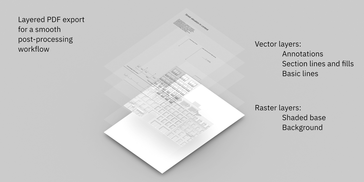
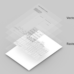
Normal PDF export creates a hybrid architectural PDF.
The current shaded viewport presentation forms the raster base, while Drawing View linework, Section graphics and annotations remain vector content.
The vector drawing is organised into three named PDF layers:
- Basic Lines;
- Section Lines;
- Annotations.
This makes the main architectural graphics easier to isolate, edit and post-process in compatible PDF or graphics applications while preserving the complete shaded presentation.
6.4. Vector Lines Only
Enable Vector Lines Only when you do not need the shaded viewport base.
For PDF export, this creates a clean vector drawing containing Drawing View linework, Section graphics and annotations without the raster model or background.
Vector Lines Only is a shared Export option in the current Blender Scene rather than a property stored separately for each Layout, so check its state before exporting.
6.5. Text and Fonts in PDF
Annotation text is exported as real embedded PDF text where the selected font supports the editable text workflow. This keeps text searchable and copyable and allows further text editing in compatible applications.
Drawing View's bundled Inter family supports this workflow.
Other installed fonts can also be used when they provide compatible static TrueType outlines and allow editable embedding.
Some OpenType/CFF fonts or fonts with restrictive embedding permissions cannot be used for editable PDF text. If an unsupported font is selected, Drawing View reports the export problem rather than silently replacing the intended result.
7. Common Workflows
7.1. Create an Elevation
- Create or select a camera facing the required elevation.
- Click Create Layout from Camera.
- Choose the page and scale.
- Refine the Layout position and composition.
- Apply Shaded Style if required.
- Run Build Lines.
- Activate Annotations.
- Add Dimensions, Elevation Marks, Scale Bars and text as required.
- Export the Layout as PNG or PDF.
7.2. Create a Section
- Create a vertical Layout.
- Move the Layout plane through the model to the required cut position.
- Run Build Lines.
- Choose Fill or Hatch and adjust Section lineweight as required.
- Add Dimensions, Elevation Marks and other annotations.
- Export the Layout.
7.3. Create a Plan
- Create a Layout looking along the world vertical axis.
- Set the required page and scale.
- Position the Layout at the required plan cut.
- Run Build Lines.
- Add Dimensions and Scale Bars where needed.
- Use Text, Header, Flag or Callout for additional drawing information.
Elevation Marks are intentionally unavailable in plan Layouts.
7.4. Update a Drawing After Model Changes
- Make the required changes to the Blender model.
- Return to the affected Layout.
- If Drawing View shows Lines need rebuild, run Build Lines again.
- Review measured annotations if the geometry they refer to has changed.
Annotations are stored separately from generated linework. Rebuilding lines does not recreate or remove the Annotation layer.
7.5. Create Dimensions Continuously
- Run Build Lines to prepare model snap anchors.
- Activate Annotations.
- Choose Orthogonal Dimension or Aligned Dimension.
- Create and place the first dimension.
- Click the next model point to begin another dimension immediately.
- Press Esc when the dimensioning sequence is finished.
7.6. Edit Text Directly on the Layout
- Activate Annotations.
- Double-click a Text, Header, Flag or Callout.
- Edit the content directly in place.
- Select a text range if only part of the annotation needs different formatting.
- Adjust Font Family, Weight, Size or other typography controls while editing if required.
- Press Ctrl+Enter to apply the edit.
7.7. Export a Clean Vector Drawing
- Enter the active Layout.
- Make sure the viewport uses Solid shading.
- Run Build Lines.
- Enable Vector Lines Only.
- Click Export PDF.
The resulting PDF contains Drawing View linework, Section graphics and annotations as vector content without the shaded raster base.
8. Capabilities and Limitations
8.1. Orthographic Drawing Views
Drawing View is built around orthographic architectural Layouts and real drawing scale.
Perspective Layouts are not currently supported as scaled Drawing View drawings.
8.2. Measured Annotations
Dimensions and Scale Bars are available in plan and vertical orthographic Layouts.
Elevation Marks are available only in vertical elevation and section Layouts.
Tilted and axonometric Layouts remain available for linework and free paper-space annotations, but Dimensions, Elevation Marks and Scale Bars are disabled.
8.3. Model Geometry and Annotations
Drawing View linework is generated from Blender model geometry.
Annotations remain separate paper-space drawing information and do not modify the 3D model.
8.4. Updating Linework
Generated linework is not recalculated continuously while the model changes.
Drawing View marks an affected Layout for rebuilding, allowing you to decide when to run Build Lines again.
Crease Threshold is an exception: after a successful Build it can adjust the visible Crease result without recalculating the complete drawing.
8.5. Linked Geometry
Linked and instanced geometry is opt-in.
Enable Linked Geometry on each Layout that should include read-only geometry linked from external .blend files.
8.6. Intersections
Intersection lines are generated between separate participating objects or mesh structures.
Self-intersections within one mesh are not generated.
8.7. Layout Duplication
Shift+D duplicates the Layout configuration as a new independent drawing view.
The source Layout's generated linework and placed annotations are not duplicated.
9. Saving and Restoring Projects
Drawing View project data is stored inside the .blend file.
Each Layout preserves its page and scale configuration, Layout-specific presentation and source settings, and annotations.
Completed linework can also be restored when compatible saved drawing data is available.
If saved line data is no longer valid after model changes or an update, Drawing View shows that the affected Layout needs rebuilding. Run Build Lines once to generate the current result.
Annotations are stored independently from generated linework and remain part of the Layout when linework is rebuilt.
10. Troubleshooting
10.1. Lines Need Rebuild
Return to the affected Layout and run Build Lines.
This status normally appears after model, Layout or Build-input changes that affect the drawing result.
10.2. Dimensions or Elevation Marks Cannot Find Model Points
Run Build Lines first. Dimensions and Elevation Marks use model snap anchors prepared during line generation.
If an older saved drawing does not contain current snap information, Drawing View may ask you to rebuild the Layout once.
10.3. Measured Annotation Tools Are Disabled
Check the Layout orientation.
- Dimensions and Scale Bars require a plan or vertical view.
- Elevation Marks require a vertical elevation or section view.
- Text, Header, Flag and Callout remain available in tilted and axonometric views.
10.4. Linked Objects Are Missing from the Drawing
Enable Linked Geometry for the active Layout and run Build Lines again.
If the linked geometry belongs to the Layout's Exclude collection, Exclude takes priority and the geometry remains excluded.
10.5. Excluded Geometry Still Hides Lines
Check Use Excluded as Mask.
When enabled, excluded objects do not create their own Drawing View graphics but their visible surfaces can still hide lines behind them.
Disable the option and rebuild the Layout if that geometry should be ignored completely.
10.6. An Expected Intersection Is Missing
Drawing View does not calculate self-intersections within a single mesh.
If the required intersection is between logically separate parts of one mesh, split those parts into separate objects where appropriate and rebuild the Layout.
10.7. Export Is Unavailable
Check that:
- a Drawing View Layout is active;
- you are currently looking through that Layout;
- the viewport uses Solid shading;
- the Layout has completed Build Lines.
10.8. PDF Export Reports a Font Problem
Use Drawing View's bundled Inter family or another compatible installed font that permits editable PDF embedding.
Some OpenType/CFF fonts and fonts with restrictive embedding permissions cannot be used by the editable PDF text workflow.
10.9. GPU Line Generation Problems
If Use CPU Backend is available in Drawing View's add-on preferences, enable it when you experience problems with GPU line generation.
The CPU backend is a compatibility option and line calculation may be slower.
10.10. Build Lines Is Slow on a Heavy Scene
Build time depends on scene complexity and the amount of geometry participating in the drawing.
Hide or exclude geometry that does not need Drawing View linework. Dense vegetation, helper geometry and high-detail context are common candidates.
11. Compatibility
Officially supported versions and platforms:
- Blender 4.5–5.2
- Windows — full feature support
Drawing View works directly inside Blender and does not require external applications or online services for its core functionality.
This documentation is current as of Drawing View 1.2.
 Included
Includes 12 months of
- Support from Arch on Arch
- Product updates
Extend this product’s Support Period +12 months: 50% of product price
Have questions before purchasing?
Login to message
| Blender Extension Compatible | Yes |
| Published | 24 days ago |
| Blender Version | 4.5 - 5.2 |
| Extension Type | Add-on |
| License | GPL |
Discover more products like this
drafting section architectural visualization pdf-export annotation architectural drawing architecture presentation Technical drawing layout linework vector