FlatPack
 Kurv Designs
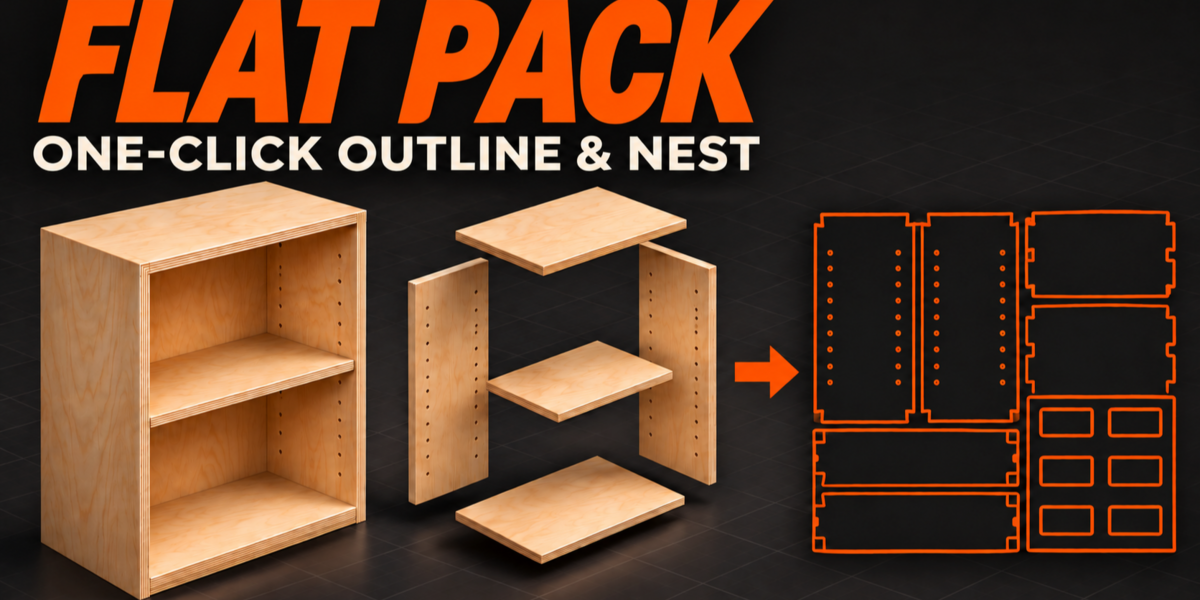
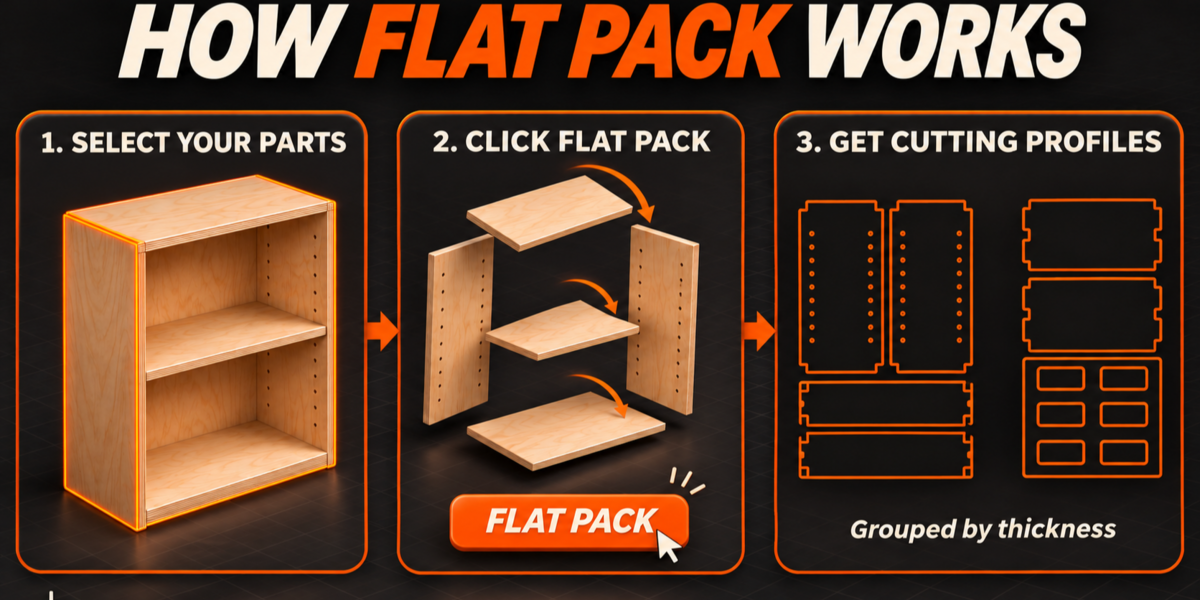
Flat Pack — Getting Started
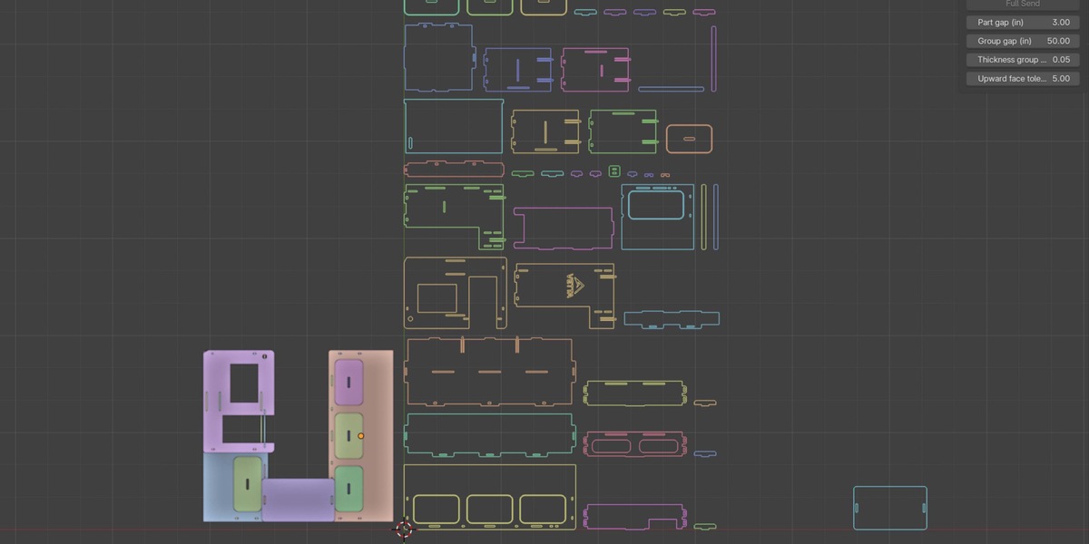
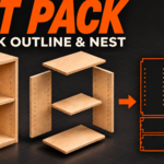
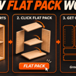
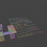
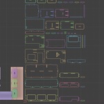
Flat Pack converts selected panel parts into editable 2D cutting profiles and arranges them by thickness. The current release appears as Full Send in Blender’s add-on list and sidebar.
Installation
Download the add-on ZIP.
Open Blender’s Edit → Preferences → Add-ons.
Choose Install from Disk from the menu and select the ZIP.
Enable Full Send.
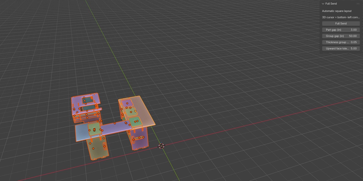
In the 3D Viewport, press N to open the sidebar, then select the Full Send tab.
Preparing your parts
Use individual objects for individual panels. Parts should be modeled flat in their local XY plane, with material thickness along local Z. You can rotate these objects into an assembled cabinet afterward.
The add-on clears object rotation when preparing profiles. Parts modeled vertically in Edit Mode, or with their assembly rotation applied, may require manual orientation before processing.
Visible modifiers, including Boolean results, are evaluated when creating profiles. Objects referenced as Boolean cutters are excluded from the layout.
Creating a layout
Switch to Object Mode.
Select the panel objects you want to process.
Position the 3D cursor at the desired bottom-left corner of the layout.
Adjust the spacing and thickness settings.
Click Full Send.
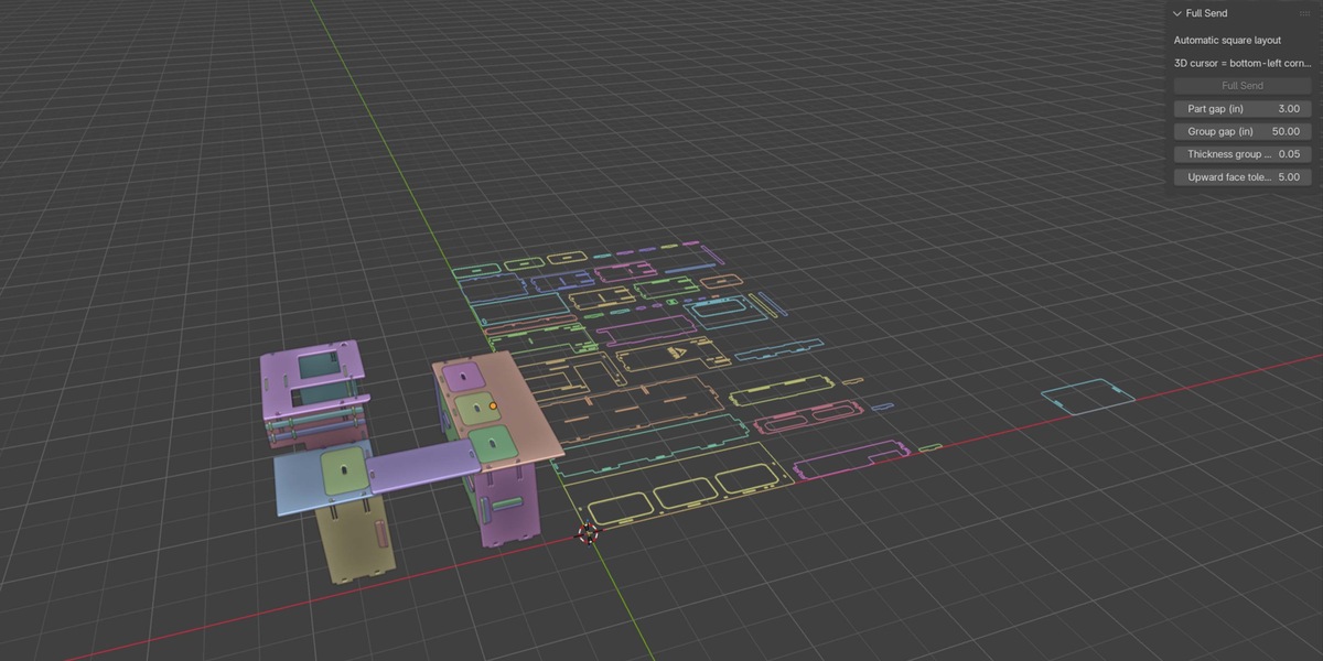
The resulting curves appear in a new Full Send Layout collection. The layout extends along the world +X and +Y axes at the cursor’s Z height.
Each run creates a new layout collection.
Settings
Part gap (in) — Spacing between packed part bounding rectangles. Default 3 inches.
Group gap (in) — Horizontal spacing between thickness groups. Default 50 inches. Effective group spacing is at least the part gap.
Thickness group span (in) — Maximum thickness difference from the thinnest part in each group. Default 0.05 inches.
Upward face tolerance (°) — Maximum angle a face’s normal can deviate from upward and still be included. Default 5°.
Spacing values are entered in inches and converted using the scene’s unit scale. Existing Blender files may retain previously saved settings.
How nesting works
Flat Pack tries several row widths to find a compact, roughly square overall layout. It packs bounding rectangles and allows 90° turns.
Thickness groups run from left to right, starting with the thinnest group. Their bottom edges align. The layout grows automatically to accommodate the parts.
The resulting shape depends on panel sizes, spacing, and the number of thickness groups.
Working with the output
The profiles are closed, editable Blender curves. Eligible holes, slots, and notches are included in the extracted boundaries.
Inspect the profiles and verify dimensions before preparing machining operations. Use your preferred export and CAM tools to create manufacturing files and toolpaths.
Troubleshooting
The button is unavailable
Switch to Object Mode and select at least one supported object.
A part produces the wrong outline
Check its local orientation. Clearing its object rotation should expose the intended panel surface toward +Z.
“Missing or branching upper perimeter”
The selected upward-facing faces could not form closed boundary loops. Inspect the named object for disconnected vertices, branching edges, unsuitable geometry, or incorrect orientation.
Parts are grouped unexpectedly
Check their actual thicknesses and adjust Thickness group span. Thickness is measured from the evaluated geometry after rotation removal.
The layout looks widely spaced
Check Part gap and Group gap. Their defaults are 3 inches and 50 inches.
Have questions about this product?
Login to message
| Published | 2 days ago |
| Blender Version | 4.3 - 5.3 |
| Extension Type | N/A |
| Render Engine Used | Cycles, Eevee |
| License | GPL |
