Image Construction
 Albert Megbenyo
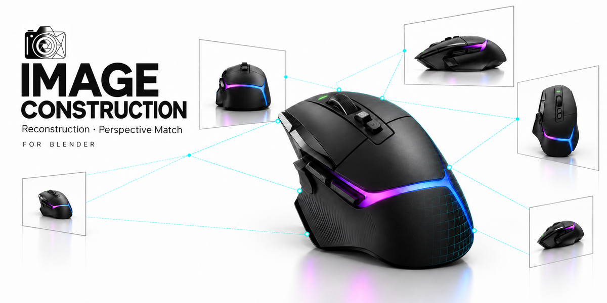
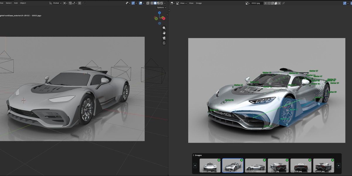
Image Construction - User Guide
Release 0.10.287. Separate Windows x64 and macOS Apple Silicon downloads. Earlier Windows release checks covered Blender 5.1, 5.2 LTS, 5.3 Beta and 5.4 Alpha; preview-build compatibility is provisional.
Contents
- A workspace built around your images
- Install and open Image Construction
- Projects, scenes and saved state
- Choose references that can be calibrated
- Import, organize and match canvases
- Thumbnails and image navigation
- Duplicates, flips and symmetry
- Quick start: from images to cameras
- Markers and image placements
- Control which data participates
- How many matches are required?
- Lens settings and metadata
- Solve modes, time and partial results
- Read colors and pixel errors
- Inspect a result while editing
- Set scale and define a floor
- Direction Axes and floor previews
- Heading, midpoints and origin
- Create the scene and compare views
- Fine-Tuning in the 3D Viewport
- Hide viewport clutter
- Quick start: match a perspective
- Place and control the guidelines
- Lens, principal point and sensitivity
- Origin and scale, precisely placed
- Work with multiple images
- Use the 3D guide effectively
- Create, center and fine-tune
- Arrange the workspace panels
- Live Guides in the camera view
- Create a multi-view modeling layout
- Main View and independent images
- View Translator
- Import from a phone or device
- Recover missing image files
- Export and import .icp projects
- Finish a model and remove its setup
- Reconstruction: inspect your own setup
- P.Match: architecture and products
- Reconstruction does not solve
- The result exists, but looks wrong
- P.Match views do not agree
- Phone connections and file recovery
- What changes what?
- Mouse, keyboard and picker guide
- Glossary
- Compatibility and support
START HERE
A workspace built around your images
Choose the calibration method that fits the reference material.
Image Construction brings reference images, camera calibration and modeling views into one Blender project. Reconstruction solves cameras and sparse 3D markers from matching points. P.Match fits cameras from perspective guidelines, an origin and a scale reference. Both workflows leave you with a scene you can model in.
| Choose Reconstruction | Use several views of the same rigid subject with recognizable points visible across views. Useful for curved products, vehicles and objects without long straight edges. |
|---|---|
| Choose P.Match | Use one or more views with clear, straight edges along perpendicular directions. Useful for architecture, furniture, appliances and other structured objects. |
| Use both in one blend | Create separate projects. Each project has its own scene and a fixed mode; it does not change mode after creation. |
What the result contains
Reconstruction creates cameras and marker empties. P.Match creates a camera for each valid image view and can also create a Plane, Cube or Cylinder guide mesh. Camera backgrounds and timeline camera markers let you compare a model against the references.
How to read this manual
Start with the quick start for your mode, then use the control chapters as a reference. Names in bold match controls or sections in the interface. Screenshots show demonstration projects; some captures precede this release, so small differences in layout are possible.
Release coveredBack to contentsImage Construction 0.10.287. Choose the installer for Windows x64 or macOS Apple Silicon. The Mac package requires macOS 13+ and native Apple Silicon Blender 5.1+; this update has not been tested natively on Mac. Intel Mac and Linux packages are not included.
START HERE
Install and open Image Construction
Install the release ZIP, then enter the dedicated image workspace.
- In Blender, open Edit → Preferences → Add-ons. Use the menu in the upper-right corner and choose Install from Disk.
- Select the Image Construction release ZIP. Install it without extracting or renaming its contents, and enable the extension if Blender asks.
- In the 3D Viewport, open the sidebar with N. Select the Image Construction tab and click Open Image Construction.
- Choose Create New Project, enter a useful name and select Reconstruction or P.Match. The project opens in a separate scene.
Your working environment
The dedicated workspace is an Image Editor with the project controls in its sidebar. Import Images is the starting section; open the other sections as you need them. Pan and zoom to place features precisely. Use Look Through Camera to return to a 3D modeling view after creating the cameras.
| Save your work | Use Blender’s normal Save / Save As commands to save the .blend, including project scenes and settings. |
|---|---|
| Update the extension | Save the blend and keep a copy of the previous release. Install the replacement ZIP and restart Blender when replacing a build to avoid mixing loaded modules. |
| Network access | Phone/device import uses a temporary connection session. Local image import and calibration do not require a phone connection. |
| Unsupported Blender version | Use the version range supported by the release. A dependency or compatibility error is not a calibration problem. |
Keep the release togetherBack to contentsThe distributed ZIP contains platform-specific dependencies. Copying only a few Python files into an existing installation is not a reliable way to install or update the add-on.
START HERE
Projects, scenes and saved state
Understand what belongs to a project before you duplicate or remove it.
A project is backed by a Blender scene. Switching projects changes the active scene, including its cameras, objects, reference images and settings. A blend can hold several projects alongside ordinary Blender scenes.
| Create New Project | Creates a separate named scene. Existing projects are retained. The chosen mode is fixed for that project. |
|---|---|
| Project selector / Open Project | Returns to a saved project scene. Use a clear Project Name so similar studies are easy to distinguish. |
| Close Active Project | Hides the active project from the working view without deleting it. Reopen it from the project selector. |
| Duplicate Project | Makes an independent copy of the project and its scene, then activates it. Useful before changing reference strategy or scale. |
| Delete Project | Deletes the active project scene and its setup. It is different from removing only the generated setup. Other scenes and original image files remain. |
| Remove Image Construction Setup | Finishing operation in Project Management → Project Cleanup. Keeps your modeled objects and, in P.Match, the guide mesh. See the cleanup chapter. |
A practical save routine
Save a working blend before a major calibration change. Duplicate a project for alternative solutions. Export an .icp when you need to move a complete setup into another blend. Export before removing a finished project’s setup if you may want to calibrate it again.
Do not confuse three actionsBack to contentsClose retains the project. Delete Project removes its scene. Remove Image Construction Setup keeps the scene and modeling work but removes the calibration setup.
REFERENCE IMAGES
Choose references that can be calibrated
Good geometry in the images matters more than a large image count.
For Reconstruction
Use overlapping views of the same rigid object. Pick features that stay physically fixed: corners, screw centers, panel intersections or distinctive texture details. Include depth variation and viewpoints that reveal different sides. A sequence of almost identical views gives weak depth, even with many marks.
For P.Match
Look for two families of straight, parallel edges that are perpendicular in the real object. The edges do not need to meet in the image. Long edges with visible convergence are easier to fit than short segments or an almost orthographic product render.
| Prefer | Sharp images, consistent object geometry, visible overlap, clean corners and enough perspective to judge depth. |
|---|---|
| Treat carefully | Reflective surfaces, repeated patterns, smooth silhouettes, retouched product renders and very wide-angle images. |
| Avoid for calibration | Fisheye or panoramic projections, changing/deforming subjects, perspective-corrected images with unknown edits, and marks placed on moving highlights. |
| Cropped references | A crop changes the relationship between image center and optical center. Use original images when possible. P.Match offers a manual principal point when the crop is understood. |
Symmetry is an assumptionBack to contentsA mirrored reference can help model a symmetric shape, but it does not reveal genuinely hidden details. Buttons, vents, logos and panel lines may differ between sides.
REFERENCE IMAGES
Import, organize and match canvases
Prepare a consistent image space before calibration.
- Use Import Images in Reconstruction or Add Image(s) in P.Match. The importers accept JPEG, PNG and TIFF still images.
- Review the image list. Rename labels to make views easy to identify; renaming a label does not rename the source file.
- If image resolutions or aspect ratios differ, run Match Image Canvases. Review the proposed resolution percentage and resulting dimensions.
- Wait for canvas preparation to finish before editing guides, placing marks or creating cameras. Use Esc if you need to cancel.
What canvas matching does
Each image is fitted proportionally onto a common canvas, with margins where necessary. It does not stretch the subject to a different aspect ratio. The original files are preserved. Existing marks or perspective guides are carried into the new image coordinates.
The initial target is derived from the largest image by pixel area. Once established, the project canvas is reused. Camera render framing uses that common canvas. Very large canvases cost memory and preparation time; reduce the resolution percentage when full resolution is unnecessary.
| Reconstruction | An unmatched canvas blocks downstream marking, solving and creation until the images are prepared. |
|---|---|
| P.Match | Match Image Canvases is available for multiple image views. Resolve canvas differences before judging consistency between camera views. |
| Limits | Reconstruction supports 2–24 enabled images and 8–500 enabled markers. P.Match supports 1–24 image views. A prepared canvas is limited to 100 megapixels. These limits do not guarantee a successful solve. |
REFERENCE IMAGES
Thumbnails and image navigation
Keep the reference sequence easy to browse while you work.
| Show Image Thumbnails | Displays the movable strip. In P.Match, thumbnail controls appear when the project contains more than one image. |
|---|---|
| Horizontal / Vertical | Changes the strip orientation. Each orientation retains its own layout. |
| Move and resize | Drag the header to move the strip. Drag its long edge to show more images, or a corner to resize the thumbnails. |
| Browse | Click a thumbnail to select it. Scroll over the strip to browse its contents. Use the arrow keys over the image workspace to change images. |
| Reorder | Use the list’s move controls or grip where available. A list grip uses click, move, click; Esc or right-click cancels. Thumbnail reordering uses dragging. |
| Reset Thumbnail Layout | Resets the current orientation’s placement and size; the other orientation is retained. |
Reordering changes presentation and camera sequence, not the meaning of a marker. Reconstruction ranks candidate additions by available matches rather than simply assuming the first image must be solved first.
Back to contentsREFERENCE IMAGES
Duplicates, flips and symmetry
Use mirrored references deliberately, and recheck the correspondences.
| Duplicate Selected Image | Reconstruction duplicates the image entry, its lens settings and marks. The disk file is unchanged. A duplicate is not a new physical viewpoint. |
|---|---|
| Flip Selected Image Horizontally | Creates a mirrored packed project copy and clears that image’s marker placements. Marks in other images remain. Place the matching markers again before solving. |
| Why marks are cleared | The same pixel position no longer represents the same physical feature after a mirror operation. Keeping those correspondences would make a misleading calibration. |
A careful symmetry workflow
Duplicate the reference if you want to keep both versions. Flip the copy, then assign markers according to a consistent symmetric-object interpretation. Inspect asymmetrical details before using them as correspondences. Solve and examine the result in all views rather than trusting a single matching silhouette.
Mode-specific behaviorBack to contentsReconstruction clears marks on a flipped image. P.Match mirrors the image and its perspective guides together, then recalculates the match. See Work with multiple images for the P.Match controls.
RECONSTRUCTION
Quick start: from images to cameras
Build a small, well-connected setup before expanding it.
- Create a Reconstruction project. Import overlapping images of the same subject and match their canvases if requested.
- Add a marker. Place it on the same physical point in each image where that point is clearly visible. Repeat with features spread across the subject and its depth.
- Make at least one strong starting pair with eight or more shared markers. Give the other views enough shared features to join the solved geometry.
- Open Solve Reconstruction. Begin with Progressive (Recommended), then run Solve Reconstruction.
- Inspect the colors, pixel errors and solve notes. Correct inaccurate marks or improve the references, then solve again.
- Set an optional known distance, floor, heading and origin in Scale and Orientation.
- Click Create / Update Reconstruction, then Look Through Camera. Begin modeling against the calibrated views.
The two stagesSolve calculates camera and marker geometry. Create / Update writes the current result into Blender objects. A solved result and an updated 3D scene are separate states.
A sensible first exercise
Use a small set of your own overlapping images to study repeated marker identities and image overlap. Duplicate the project before experimenting. Move a mark slightly, observe the stale-result notice, solve again and compare the error feedback.
Back to contentsRECONSTRUCTION
Markers and image placements
One marker is one physical feature; each mark is its placement in an image.
A marker can have placements in two, three or many images. It does not need to appear in every reference. The important rule is identity: Marker 01 must always refer to the same physical point, not whichever nearby corner is easiest to see.
| Add Marker | Creates a new marker identity. Select it and click the appropriate point in the current image. |
|---|---|
| Click and drag | Places or moves the selected mark. Hold Shift while dragging for slower, more precise movement. Release to accept; Esc or right-click cancels an active drag. |
| Right-click a mark | Selects that existing marker so you can inspect or edit it. |
| Pixel X / Pixel Y | Numerical image-space position for the selected placement. Y is measured from the top of the image. |
| Follow | Keeps the selected marker centered when changing images or markers, preserving zoom. If a view has no placement for that marker, its view is retained. |
| Magnifier While Dragging | Shows a magnified patch and crosshair for precise placement. It does not add information beyond the source image. |
What makes a reliable point
Use a corner you can identify independently in each image. Avoid points on a smooth silhouette: the visible contour of a curved surface can come from different physical points as the viewpoint changes. Reflections and highlights are similarly unreliable.
Back to contentsRECONSTRUCTION
Control which data participates
Disable uncertain data before deleting it.
| Include Image In Solve | Excludes or includes the entire image while preserving its saved marks. |
|---|---|
| Include Marker In Solve | Excludes or includes that marker across every image. Its placements remain saved. |
| Use Mark In Calibration | Excludes only the selected placement in the current image; the marker remains available in other views. |
| Lock Marker | Prevents adding, moving or removing placements for that marker. It is an editing lock, not an exclusion from calibration. |
| Lock / Unlock All Markers | Applies the placement lock across the marker set. The button changes to Unlock when all are locked. |
| Remove Mark From This Image | Deletes only this image’s placement of the selected marker. |
| Delete a marker / Delete All Markers | Deletes the marker identities and their placements across images. Existing 3D objects are not immediately rebuilt. |
| Remove image / Remove All Images | Removes the project image entries and their marks. Original files are kept. |
Keep the list readable
The marker-list column controls let you show or hide Lock, Include In Solve, Reprojection Error and View Count. Hiding a column changes only the interface, not any marker’s settings. Names and ordering help organization; they are not geometric constraints.
Troubleshooting without losing workBack to contentsTurn off a doubtful placement or marker, solve again and compare. This is usually easier to reverse than deleting all its observations.
RECONSTRUCTION
How many matches are required?
The starting pair and later cameras have different requirements.
| Project validation | 2–24 enabled images and 8–500 enabled markers. The image graph must be connected by shared marker identities. |
|---|---|
| Starting pair | At least one pair must share eight fitting markers. The current implementation retains this requirement even when lens values are known. |
| Other views: Automatic or Approximate lens | At least six fitting marks shared with other enabled images are required by validation. Joining the 3D result also depends on usable reconstructed correspondences. |
| Other views: Known / Fixed lens | A four- or five-correspondence fallback is available for camera registration. It requires a trusted fixed lens and an unambiguous, geometrically valid pose. |
| Each marker | A marker can be reconstructed from two suitable views. Eight is not the number of images each marker needs. |
| Coverage | Marks must span the image, not sit in a tiny cluster or almost one line. Current validation checks at least 12% of content width and height. |
The initial global lens-estimation pass needs a usable eight-match pair for each free lens. If it fails, incremental solving can start with a stronger subset and add later views from reconstructed 3D points. This is why a lens-initialization message can mention eight even though later camera registration accepts six.
Pending cameras are ranked by available reconstructed matches, strongest first. A numeric minimum does not guarantee useful depth, consistent geometry or a stable lens estimate.
Practical targetBack to contentsPrefer more than the minimum, spread across visible depth and both image dimensions. If a camera has only four reliable marks, treat that as a fallback case—not the ideal reference set.
RECONSTRUCTION
Lens settings and metadata
Use a known lens only when the value describes the image you actually imported.
| Automatic | Estimates focal length from matching marks. Begin here when no reliable focal information is available. |
|---|---|
| Approximate | Uses the entered equivalent focal length as a starting estimate and allows refinement. |
| Known / Fixed | Keeps a trusted equivalent focal length fixed. This enables the four/five-match registration fallback for additional views. |
| Lens (35mm Equivalent) | The Reconstruction field expects a 35mm-equivalent value, not necessarily the physical focal length engraved on a small-sensor camera lens. |
| EXIF source note | When suitable metadata is available, the add-on can populate an equivalent focal value. Read the note and verify that the image has not been cropped or digitally transformed. |
Why a value can appear automatically
A JPEG may store the camera’s equivalent focal length in its EXIF metadata. Selecting an advanced lens mode can reveal a value already obtained from that metadata. The add-on is reading the image information; it is not recognizing the device by its appearance.
When not to trust it
A screenshot, edited crop, digital zoom or downloaded marketing image may have absent or misleading metadata. Different phone camera modules also use different lenses. Enter a value for the actual image, not a single universal number for a phone model.
Known is a constraintBack to contentsA wrong fixed lens can make a good marker set fail or distort the result. If the value is only an estimate, use Approximate or return to Automatic.
RECONSTRUCTION
Solve modes, time and partial results
A paused search is different from impossible geometry.
| Progressive (Recommended) | Starts with a 3 px tolerance. After unsuccessful searches, it can relax through 6, 12, 24 and 48 px within the shared time budget. |
|---|---|
| Custom | Uses your fixed Solve Tolerance and Minimum View Angle instead of progressive tolerance levels. |
| Solve Tolerance (Pixels) | Controls fitting and acceptance. A larger tolerance can admit less accurate observations; it does not repair wrong correspondences. |
| Minimum View Angle (Degrees) | Rejects triangulation with too little separation between viewing rays. Very small angles produce weak depth. |
| Search budget | A solve receives 10 minutes. Continue Trying (10 minutes), when offered, resumes unfinished search work. |
| Esc | Requests cancellation. The previous result is preserved rather than replacing it with an unfinished calculation. |
Inspect a partial solve
A result may calibrate some images while leaving others out. Read the status and solve notes, inspect which cameras were created, and check the unresolved images for shared points, placement accuracy, lens settings and viewpoint separation. Continuing a search helps unfinished attempts; it does not add missing evidence.
Do not judge by “completed” aloneBack to contentsProgressive mode may succeed at a relaxed tolerance. Inspect the actual RMS, excluded observations and visual alignment before accepting the result.
RECONSTRUCTION
Read colors and pixel errors
Use feedback to find inaccurate observations, not to chase a color.
| Green | Error at or below Good Threshold. Default: 3 px. |
|---|---|
| Amber / yellow | Above Good Threshold but at or below Poor Threshold. Default: 6 px. |
| Red | Above Poor Threshold or excluded from fitting. Inspect the selected mark and solve notes. |
| White | Not evaluated or disabled; it is not a confirmation of accuracy. |
| Fit RMS | Aggregate reprojection error of the fitted result, in pixels. |
| This Image / Fitted / Excluded | Image-level RMS and counts of included versus excluded observations. |
| Selected Mark Error | Distance between the placed mark and the model’s predicted image position. |
| Color Thresholds | Display thresholds only. Changing them does not change the solve or improve its accuracy. |
A reliable correction loop
Select a high-error mark, zoom in, and compare that same marker in its other images. Check the physical identity before nudging a position. Correct or disable the bad observation, solve again, then inspect the remaining errors. One or two badly identified markers can disturb many cameras.
Low error has limitsBack to contentsA small pixel error is agreement with the fitted image observations. It is not proof of correct dimensions, lens distortion, symmetry assumptions or real-world measurement accuracy.
RECONSTRUCTION
Inspect a result while editing
Retained diagnostics help you make several corrections without losing context.
Moving, adding, disabling or removing calibration data can make the solution stale. The workspace shows Reconstruction needs updating and disables operations that require a current calibration. Colors and pixel errors from the last solve remain available for inspection, with a notice that they are from the previous result.
| Retained errors | Use them as a record of the last solve. They are not newly calculated errors for a mark you have just moved. |
|---|---|
| Show Markers | Controls the image overlay, including matching marks and error lines. It does not remove observations. |
| Epipolar Guides | Uses an existing valid calibration to show possible matching lines for the selected feature. A line narrows the search; it does not identify the correct physical point. |
| Show Off-Cam Markers | Shows faint projected positions for reconstructed markers that are not placed in the current image. Edge arrows indicate positions beyond the image. |
| Off-Cam colors | Reflect overall marker error, not a measured error in a view where no mark exists. Occlusion is not tested. |
Use predicted markers carefully
A projected marker can appear over a hidden surface. Do not add a mark just because a faint circle is visible. Confirm the feature in the actual image first. Picking an Off-Cam circle for an orientation field assigns the existing 3D marker; it does not create a new calibration observation.
When you finish correctingBack to contentsRun Solve Reconstruction again, review the fresh diagnostics, then Create / Update Reconstruction to refresh the scene.
RECONSTRUCTION
Set scale and define a floor
These controls orient the solved geometry; they do not recalibrate the images.
Set a known distance
In Scale and Orientation → Set Scale, select two reconstructed markers, enter their Known Distance in scene units and click Apply Scale. Cameras and points scale together. This changes size, not shape or the quality of calibration.
| Three Markers | Select three distinct, non-collinear reconstructed markers on the intended floor plane. Complete valid selections update the orientation preview. |
|---|---|
| Four Corners | Select four corners of a rectangular floor reference. The slots are ordered automatically while A remains first. The method fits a floor from the corner geometry. |
| Direction Axes | Uses two pairs of parallel edges in a calibrated image to establish floor tilt. See the next page. |
| None | Uses two axis markers without a floor constraint. Floor Tilt rotates around the chosen alignment axis. |
| Floor Perpendicular Axis | Chooses the world axis normal to the floor: Z for an XY floor, X for YZ, or Y for XZ. |
| Flip Floor Up Direction | Reverses which direction is considered above the floor. |
Pick stable referencesBack to contentsChoose well-reconstructed points separated across the object. Three points nearly in a line give an unstable floor. A wheel or roof marker defines a plane at that height—not automatically the ground under the object.
RECONSTRUCTION
Direction Axes and floor previews
Separate the geometric floor from its visual aid.
Define a floor using Direction Axes
- Choose a calibrated reference image with useful parallel edges. Select it as the floor-axis source.
- Place two A segments along one parallel direction and two B segments along the other. These are direction references, not additional matching markers.
- Use Snap To Markers to link endpoints to nearby marks. Hold Alt while releasing to keep an endpoint free.
- Use Swap Axes or Reverse Axis A / B if the orientation is wrong. Choose a Floor Height Marker if the floor must pass through a particular reconstructed point.
| Floor Height Offset | Moves the geometric floor along its normal relative to its references or height anchor. |
|---|---|
| Show Floor Viewer / Floor Opacity | Displays or fades the visual plane or volume in the image workspace. |
| Plane / Cube / Cylinder | General visual references. Size, length, width, height and planar viewer offsets change the preview, not the calibrated shape. |
| Triangle | Available with Three Markers; shows the selected floor triangle. |
| Bounds | Available with Four Corners; shows the projected A–D bounds. |
| Reset Axes On Selected Image | Restarts the direction guides on that reference image. |
Two different offsetsBack to contentsFloor Height Offset changes the orientation setup’s floor reference. Viewer offsets only reposition the displayed aid along the floor.
RECONSTRUCTION
Heading, midpoints and origin
Give the result a meaningful direction and a predictable center.
| Two Markers | Select Axis Start and Axis End. Their direction defines the chosen positive alignment axis; with a floor it is projected onto that floor. |
|---|---|
| Two Line Midpoints | For the Three Markers floor workflow, define Line 1 and Line 2 with two markers each. The axis joins their midpoints. Faint connector lines help identify both pairs. |
| Four Corners heading | Choose Two Corners, or Opposite Edge Midpoints between A–B and C–D or B–C and D–A. |
| Align To / Reverse Axis Direction | Assign the heading to X, Y or Z where compatible with the floor, then reverse it if required. |
| Use Axis Midpoint as Origin | Uses the midpoint of the chosen axis reference, projected onto the floor where applicable. It temporarily takes precedence over the separate origin controls. |
Set Origin
None (Default) uses the floor center, or the axis midpoint when no floor is defined, and ignores saved manual origin markers and offsets. Single Marker uses one reconstructed marker. Average Of 2, 3 or 4 uses the mean of distinct selected markers. With a floor, the origin is projected onto it.
Planar origin offsets are available for an unassigned Single Marker origin. They are not a universal XYZ displacement of every explicit origin choice. Reset Orientation returns to the stored calibration orientation while preserving scale and the saved selections.
Finish the updateBack to contentsAfter changing scale or orientation, use Create / Update Reconstruction when the workspace says the changes are ready to apply to the 3D scene.
RECONSTRUCTION
Create the scene and compare views
Turn the current calibration into Blender cameras and marker empties.
- Open Create / Update Reconstruction and review Fit RMS, the selected image’s fit counts and the solved lens.
- Click Create / Update Reconstruction. Generated cameras and fixed marker empties are created or refreshed.
- Choose Look Through Camera. The selected image becomes the active camera reference with matching render dimensions.
- Use the generated timeline camera markers to move between reference cameras. The image sequence and frame range are set up from the project views.
The linked image and 3D views help you inspect the same reference while modeling. Camera backgrounds are a viewport aid; they are not automatically a renderable object or a finished material setup.
Updating replaces helper transformsBack to contentsManual transforms on generated cameras and marker empties can be overwritten by Create / Update. Use the project’s calibration controls and Fine-Tuning for deliberate setup changes.
RECONSTRUCTION
Fine-Tuning in the 3D Viewport
Adjust the generated setup without changing image observations.
Open the Image Construction tab with N. Fine-Tuning contains the setup adjustments; Modeling contains View Translator and viewport layouts; Project Management contains export and cleanup.
| Lock / Unlock 3D Viewport Editing | Protect generated cameras and markers from accidental selection. User-modeled objects remain available. |
|---|---|
| Flip Floor Direction | Reverse the generated setup’s floor direction. |
| Display | Image Opacity affects project camera backgrounds. Camera Display Size changes camera outlines, not framing. |
| Marker Display Type | Choose Plain Axes or Sphere. Marker Display Size adjusts all generated marker displays; Marker X-Ray shows them through meshes and is off by default. |
| Move & Rotate | Choose the Pivot, then translate or rotate the setup. Moving the 3D cursor when it is the pivot does not itself move the reconstruction. |
| Scale | Use Uniform Scale, or enable Scale By Two Markers and enter their desired distance. |
| Align Axis | Use two markers and a chosen axis. Swap reverses their order; the angle control adds rotation about that axis. |
| Reset Fine-Tuning | Return adjustments to their baseline. This does not improve or change the original image observations. |
Display, Move & Rotate, Scale and Align Axis start collapsed. After rebuilding a reconstruction, Apply Previous or Reset To Defaults determines whether earlier adjustments are retained. Floor definition remains in the Image Editor’s Scale and Orientation panel.
Back to contentsRECONSTRUCTION
Hide viewport clutter
Keep the reference images and markers visible while reducing visual distractions.
Open Fine-Tuning > Display in the 3D Viewport. The four choices control which helpers are hidden, not which items are kept.
| None (Default) | Do not apply clutter hiding. Returning to this option restores the previous floor, axes and camera visibility. |
|---|---|
| All (Markers Left) | Hide the floor grid, world axis lines and unused camera outlines together. Reference images, marker empties and modeled meshes remain visible. |
| Cameras Only | Hide unused camera outlines. Cameras needed by visible reference views remain available so their background images continue to display. |
| Floor Only | Hide the floor grid and world axis lines. Keep camera visibility unchanged. |
Use it while reviewing a model
- Look through a project camera, then choose All (Markers Left) to compare the mesh with the image without the surrounding camera outlines and grid.
- Use the arrow keys or image thumbnails to move through references. The active camera background follows the view.
- Choose None (Default) when you need the normal helpers again.
Visibility onlyBack to contentsThese controls do not delete cameras, alter calibration or change your rendered geometry. Marker X-Ray and Marker Display Size remain separate controls. A camera in use by another visible viewport may still be visible there.
P.MATCH
Quick start: match a perspective
Start with two vanishing points, then choose another mode when the image calls for it.
- Create a P.Match project and use Add Image(s). For several views, use two- or three-point mode.
- In Perspective Guides, choose 2 Vanishing Points. Assign Axis A and Axis B to different signed world axes.
- Place A1–A2 and A3–A4 on two parallel edges for Axis A. Place B1–B2 and B3–B4 on two parallel edges for Axis B.
- Place O at a recognizable corner. Under Set Scale from O to R Axis Along, choose the measured direction and place R at the endpoint.
- Enter Reference Length. Enable Show 3D Guide and size the preview to inspect the fit.
- Enable Import 3D Guide Mesh if wanted, then click Create Setup. Use Look Through Camera to begin modeling.
After the first creationValid guide, origin, lens and scale changes update existing cameras automatically. Update Setup becomes available when cameras are missing, new images need cameras, or another guide mesh is requested.
Each pair of guide segments represents parallel lines in the real subject. Perpendicular world axes usually do not look perpendicular in the image.
Back to contentsP.MATCH
Place and control the guidelines
Use real structural edges and make the handles easy to read.
| Axis A / Axis B / Axis C | Assign signed world axes to guide families. Axis C appears in three-point mode. Conflicting choices are resolved automatically to keep distinct axes; the two most recently changed assignments take priority. |
|---|---|
| Guide segments | Two segments describe each measured direction: A1–A4, B1–B4 and, in three-point mode, C1–C4. |
| Show Guides | Hide or show the guide overlay without deleting its placements. |
| Axes Guide Appearance | Adjust Handle Size and Line Thickness. Choose solid or hollow handles; Reset Appearance restores defaults. These controls affect both editors. |
| Direction gizmo | The axis gizmo at the origin indicates world directions. Its on-screen size stays readable independently of guide-mesh dimensions. |
| Drag Target | Limit Image Editor dragging to particular handles when they overlap. |
| Lock Guidelines | In the Image Editor, endpoints can slide along locked lines. Viewport Live Guides allow free placement while Guiding is active. |
| Reset Guides | Restore the active image’s initial guide arrangement. Other image views retain their own placements. |
Use the longest reliable edge sections, avoid rounded corners and soft shadows, and zoom in for final placement. Guide extensions meet at their vanishing point instead of continuing beyond it.
Back to contentsP.MATCH
Lens, principal point and sensitivity
Choose one, two or three vanishing points to suit the available perspective evidence.
| 1 Vanishing Point | One image and a known focal length. Place the A guide pair, choose the Up Axis and use Roll or the horizon handles to orient the view. |
|---|---|
| 2 Vanishing Points | Two perpendicular direction families. Automatic estimates focal length using the principal-point setting; Known Lens uses your entered focal length. |
| 3 Vanishing Points | Three perpendicular direction families. Automatic estimates focal length and principal point from the guides. Known Lens is also available. |
| Focal Length readout | Updates as valid guide placements change. An invalid or degenerate arrangement cannot provide a reliable value. |
| EXIF initialization | Suitable 35mm-equivalent metadata supplies a starting value, converted to P.Match’s horizontal 36 mm sensor convention. |
| Principal Point | Image Center or Manual is available where applicable. In three-point Automatic mode it is calculated from the guides. |
| Automatic Lens Is Sensitive | Small placement changes can strongly affect the estimate. Check crop and edges, or enter a trusted known lens. |
Mode changesSwitching to one-point mode requires a known lens. Returning to two- or three-point mode restores the prior lens-mode choice. One-point mode does not support a multi-image project.
Reconstruction uses a 35mm-equivalent lens field; P.Match uses a horizontal 36 mm sensor convention. Check the convention before copying values between modes.
Back to contentsP.MATCH
Origin and scale, precisely placed
Use consistent physical references while keeping image placement independent.
| O | Place the origin on the same physical point in every image. The pixel coordinates will normally differ. |
|---|---|
| R | The reference endpoint lies along the chosen signed axis from O. It moves along that direction, rather than forming a freely oriented line. |
| Set Scale from O to R Axis Along | Choose the shared measured direction. Reference Length is the shared physical distance; Fine-Tuning places that field under Set Scale. |
| Origin Position | The Image Editor and Fine-Tuning expose linked values. The two floor-axis fields share one row; the perpendicular axis is labeled Floor Height. Letters follow the selected floor plane. |
| Dragging handles | Place O and R in the active image. Other images keep their individual handle placements. Moving O carries its connected reference with it. |
| Scene offsets | O and R in the workspace and viewport follow project translation and floor-height adjustments. The displayed origin also accounts for manual camera displacement. |
If images disagreeBack to contentsVerify that O and R identify the same physical endpoints and the axis signs mean the same thing in each view. Matching screen coordinates does not establish a shared world position.
P.MATCH
Work with multiple images
Independent camera fits share an origin, reference length and guide volume.
- Use two- or three-point mode and add your reference views. Place each view’s guides on reliable parallel edges.
- Use the same physical O and R endpoints and a consistent reference direction and length across the images.
- Compare the shared 3D guide from every angle. Correct the individual guide placements where views disagree.
- Create Setup once. When adding another image later, use Update Setup to create its missing camera.
| Canvas matching | If images arrive together before calibration work begins, match their canvases as prompted. Once an image has been adjusted, new images use the established working canvas so existing placement is preserved. |
|---|---|
| Compact image controls | The strip beside the list contains remove, duplicate, flip and move up/down. Import From Phone/Device sits directly below Add Image(s). |
| Duplicate | Copies the image entry and its guide settings. The duplicate has a distinct identity and no shared camera; Update Setup creates its camera. One-point mode and the 24-image limit restrict duplication. |
| Flip | Mirrors a packed copy and the guide placements, O, R and principal-point placement together. Axis directions are adjusted and the camera match is recalculated. Source files and other image entries are preserved. |
| Remove | Removes the view entry; it preserves the source image and generated objects. Project Cleanup is the separate finishing operation. |
Mirrored referencesBack to contentsUse a flipped view only where the subject’s symmetry supports it. Mirroring an image does not create new photographic evidence or reproduce asymmetric details.
P.MATCH
Use the 3D guide effectively
A shared volume makes perspective and proportion easier to evaluate.
| Floor Plane XY / YZ / XZ | Selects the plane of the guide’s floor. The remaining axis is its height direction. |
|---|---|
| Show 3D Guide | Toggles the preview. The import-mesh option is unavailable when the guide is hidden. |
| Plane / Cube / Cylinder | Chooses the visual guide shape. Cube exposes two floor dimensions and height; Cylinder exposes diameter and height. |
| Opacity | Fades the guide overlay without changing the source image or camera calibration. |
| Size / axis sizes | Sets the actual guide dimensions in scene units. Dimension labels follow the selected floor plane. |
| Extend From Origin | For Plane and Cube, anchors the guide at O and extends it from that corner. The planar offset controls are disabled while it is active. |
| Negative size values | Choose extension toward a negative world direction. Drag the numerical size field through zero or enter a negative value. A zero-sized guide is not a useful volume. |
| Axis offsets | Moves the preview along its floor axes when it is not anchored with Extend From Origin. |
Guide dimensions and shape are shared across P.Match views. This allows a single box or cylinder to be checked from multiple cameras. The guide is an aid to assessing the match, not evidence that a rounded or irregular object has exactly that geometry.
Import deliberatelyEnable Import 3D Guide Mesh when you want this guide as scene geometry or a modeling starting point. Leaving it off keeps the guide as a workspace preview.
Offsets Detected appears beside Extend From Origin when Origin Position offsets are present. The warning is red only while Extend From Origin is checked. Click the warning for guidance; check those position values if the guide does not start where expected.
Back to contentsP.MATCH
Create, center and fine-tune
Create missing setup parts; refine existing cameras live.
| Create Setup / Update Setup | Create Setup appears when no setup remains. Update Setup repairs missing parts or adds cameras for new images. It is disabled when nothing needs creating. |
|---|---|
| Live updates | Valid edits update existing cameras. You do not need to press Update Setup after every guide adjustment. |
| Import 3D Guide Mesh | Each enabled request imports a new guide mesh and then unchecks itself. Existing guide meshes and user edits are preserved. |
| Center Project | Centers from the calibrated guide baseline. Available only with an eligible, unmodified guide; it is disabled when that guide has been modified. |
| Center Project at World Origin | Applies centering during guide creation. An existing eligible guide can also be centered through Fine-Tuning. |
| Selectable / Unselectable (Cameras) | Toggle selection protection for project cameras. Guide meshes are separate modeling objects. |
| Origin Position / Set Scale | Adjust the linked position values or shared Reference Length. These are also accessible in the Image Editor. |
| Display | Camera Image Opacity affects camera backgrounds; Camera Display Size affects their outlines. Images-panel opacity affects the Image Editor references. |
Fine-Tuning also groups Perspective Guides, Axes Guide Appearance and Live Guides. The dropdown groups start collapsed. Modeling and Project Management are separate viewport panels.
Back to contentsSHARED WORKFLOWS
Arrange the workspace panels
Native Blender panels give each stage its own space.
The Image Editor uses independent collapsible panels. Drag a panel header by its grip to rearrange it. The headings are unnumbered, so their labels remain useful after reordering.
| Reconstruction order | Image Construction; Images; Markers; Solve Reconstruction; Scale and Orientation; Create / Update Reconstruction. |
|---|---|
| P.Match order | Image Construction; Images; Perspective Guides; Origin and Scale; Match Camera. |
| Initial open state | Project controls and Images are open. The later workflow panels start collapsed. Blender can remember a saved arrangement and open state. |
| Last workflow panel | Reconstruction keeps its solve notes and export/duplicate/delete actions with Create / Update Reconstruction. P.Match keeps project actions with Match Camera. |
| Viewport order | Image Construction; Fine-Tuning; Modeling; Project Management. These are separate panels in the Image Construction tab. |
| Viewport defaults | The four main panels start open, with Fine-Tuning’s internal groups and Project Cleanup collapsed. Existing saved layouts may differ. |
Open Image Construction returns to the image workspace. Fine-Tuning adjusts the setup; Modeling manages view-based editing and layouts; Project Management contains export and cleanup.
Back to contentsP.MATCH
Live Guides in the camera view
Refine the camera from the viewport while keeping the image workspace in sync.
- Create the camera setup and enter a project camera view. Open Fine-Tuning → Live Guides.
- Click Live Guides. The button becomes Guiding… and the handles become editable in the camera view.
- Move the guides, O or R. Valid edits update the matched camera and the corresponding Image Editor placements.
- Click Guiding… again to finish. Handles become read-only; Display Guidelines returns to its previous on/off state.
| Display Guidelines | Shows the overlay without allowing edits. While Guiding is active, it is checked and disabled. Its earlier state is restored when guiding ends. |
|---|---|
| Free viewport placement | The Image Editor’s Lock Guidelines sliding restriction does not limit viewport handle movement during Guiding. |
| Axes Guide Appearance | Handle Size, Solid/Hollow handle type and Line Thickness apply in both editors. The origin axis gizmo keeps a consistent screen size. |
| One-point horizon | The horizon handles H1/H2 and Roll describe the same orientation adjustment. Use them to match the image’s level direction; this mode still needs a known focal length. |
Guiding versus displayingBack to contentsAn overlay that is visible but will not drag may simply be in display-only mode. Check the Live Guides button before changing the match.
SHARED WORKFLOWS
Create a multi-view modeling layout
Compare several camera angles without repeatedly switching one viewport.
- Create the project cameras first. With more than one image, open Modeling and click Create Views in the viewport you want to split.
- Choose Number of Images to use the full project image count, or Manual to enter an exact count.
- For Number of Images, enable Round Up to Even if you want an extra pane for an odd count. Manual has no rounding option.
- Confirm. The original viewport area is split into independent camera views. Other editors remain in place.
| Count and available space | There is no four-view cap. The requested layout must fit the available area; use fewer views or enlarge it if Blender cannot fit the panes. |
|---|---|
| Extra panes | When there are more panes than image cameras, cameras repeat. The minimum layout is two views. |
| Create Views again | Replaces the existing generated layout; it does not keep adding panes. Run it from a generated project viewport. |
| Collapse Views | The red button joins the managed layout back into one viewport while preserving unrelated editors. |
| New pane defaults | The N sidebar is closed, with Image Construction preselected for when you press N. The T toolbar is collapsed. The original pane keeps its previous sidebar open/closed state. |
Let the layout controls manage the panesBack to contentsManual splitting, joining or changing editor types can prevent safe collapse. Restore the managed panes or rebuild the layout before using its update/collapse controls.
SHARED WORKFLOWS
Main View and independent images
Choose one viewport to follow the Image Editor; keep the others on useful angles.
| Main View | Replaces Sync with Image Editor. Initially checked only in the original generated viewport. |
|---|---|
| Transfer the main view | Check Main View in another generated pane. The previous pane is unchecked automatically; the new main pane follows the currently selected project image. |
| Image dropdown | Choose the image shown in that pane. A non-main pane keeps its chosen camera independently of Image Editor navigation. |
| Selecting in the main pane | Its Image selection also changes the active image in the Image Editor. The other panes keep their own choices. |
| No main pane | Uncheck Main View if you want every generated pane to stay independent. Check a pane again to resume sync. |
| Arrow keys: Image Editor | Cycle reference images, wrapping from the last back to the first and vice versa. |
| Arrow keys: 3D Viewport | Use Blender’s normal timeline navigation. Frames can continue beyond the image-camera range; the add-on does not wrap them back to the first image. |
The main designation is scoped to the generated layout. Image choices are local camera selections, not duplicate cameras or extra calibration views.
Main View is not View TranslatorBack to contentsMain View controls image/camera selection sync. View Translator separately captures a camera or view to constrain movement. Changing one does not mean recapturing the other.
SHARED WORKFLOWS
View Translator
Move along a captured viewing direction while checking the result from another angle.
- In the viewport you want to use as the source, click View Translator in Modeling. It becomes Translating View….
- Select the object or mesh vertices you want to adjust. Press G to move along the captured viewing rays. Use Shift for finer movement or type a distance.
- Inspect from another viewport if helpful. The captured source stays fixed even when you switch cameras, change timeline frames or orbit the source viewport.
- Confirm or cancel the move normally. Turn the translator off with its button or the assigned disable shortcut when finished.
| Camera or free view | The source can be a camera or a normal viewport. Perspective movement follows viewing rays; orthographic movement follows parallel view directions. |
|---|---|
| Highlight Source View | Optional green frame for the captured camera when it is displayed. A free-view source has no camera-frame highlight. |
| Ctrl+W | Enable or recapture from the viewport under the pointer. Recapturing does not first turn the mode off. |
| Ctrl+Shift+W | Disable View Translator. |
| Shortcut conflicts | A conflicting shortcut is left unassigned. Customize the bindings in the add-on preferences or Blender keymap. |
| Apparent size | Moving closer to or farther from a perspective camera changes apparent size. Object scale is not changed by the translation. |
A pinned sourceBack to contentsIf the movement direction seems unexpected, recapture the intended view. Switching to a different camera does not automatically replace the source you selected.
SHARED WORKFLOWS
Import from a phone or device
Scan the QR in Blender, choose images and send them into the project.
- Keep the receiving Image Construction project active. Click Import From Phone/Device in the Images section.
- Scan the QR code displayed inside Blender. Open the transfer page on the sending device.
- Wait for the page to report that it is connected to Blender. Choose the images you want to import and press Send to Blender.
- Keep the session and receiving project open until the images are imported. The phone page reports Images imported and the session closes automatically.
| Accounts | End users do not need to create a Cloudflare account or enter service keys in the current interface. |
|---|---|
| Transfer path | The devices establish a direct connection where their network conditions allow it, including compatible local or different-network connections. Relay fallback is currently disabled. |
| Supported files | JPEG, PNG and TIFF. The receiver allows up to 24 files per session, 32 MiB per file and 512 MiB total. Both modes enforce a 24-image project limit. |
| Session handling | End Device Session closes it manually. Sessions also stop after 30 minutes of inactivity or when a different blend is loaded. |
| Imported files | Received images are packed into the project. Save the blend after import to retain the project changes. |
If you switch projectsBack to contentsReceived files can wait in a queue. Return to the receiving project so Blender can import them. Receiving bytes and importing images are separate steps.
SHARED WORKFLOWS
Recover missing image files
Relink original images without rebuilding your calibration work.
A blend can store a path to an image instead of storing its pixels. Moving the blend alone may break a relative path; moving or renaming the source image can break an absolute path. A checkerboard with existing guides can mean the setup remains intact but the image is unavailable.
- Find the red missing-image recovery area above the image controls, or in Fine-Tuning. Choose Relink Image Files / Relink Missing Images.
- Choose the actual folder containing the original images. The add-on searches its subfolders.
- Read the result. If an image is unresolved, check its original filename, extension, dimensions and whether more than one candidate was found.
- After recovery, verify the image content visually and save the blend in its new location.
| Not found | The exact expected filename is absent from the chosen search tree. Check redirected Desktop folders, cloud-sync locations and renamed downloads. |
|---|---|
| Multiple matches | Choose a more specific folder that contains only the intended original. |
| Different dimensions | Use the original image dimensions. A resized replacement is not safely interchangeable with existing placements. |
| Missing working canvas | A missing prepared P.Match canvas may need recovery from a saved packed project; substituting its source file is not equivalent. |
| Packed images | Their pixels travel with the blend or .icp. A missing external file does not necessarily make the packed reference unusable. |
Name matching is not content matchingBack to contentsA file with the same name and dimensions could still be the wrong image. Confirm the recovered reference before continuing.
SHARED WORKFLOWS
Export and import .icp projects
Move a project into another blend without replacing that blend.
- Select the project you want to move. Choose Export Project from the project controls or the viewport’s Project Management panel.
- In the confirmation dialog, choose Project Setup Only or Entire Project Scene.
- Choose the destination and save an .icp file. Resolve missing image files if the exporter cannot pack them.
- In the destination blend, choose Import Project and select the .icp. The project is imported as a separate scene.
| Project Setup Only | Includes images, calibration settings, markers, generated cameras and the guide mesh. Does not include unrelated modeled scene objects. |
|---|---|
| Entire Project Scene | Also includes scene objects, materials, modifiers and animation belonging to that scene. It does not mean every unrelated scene in the source blend. |
| Packed images | Supported still images are packed for transfer. JPEG/PNG/TIFF references do not need to remain at their original disk location. |
| .icp format | A dedicated Image Construction project container with a version header and integrity check. Use the add-on’s Import Project command. |
| Legacy .blend import | The importer can also append Image Construction project scenes from a blend. Non-project scenes are not imported as projects. |
Not an encryption systemThe .icp extension identifies the project format; it is not password protection or a confidentiality guarantee. Renaming it to .blend does not convert the container into a normal Blender file.
External simulations, linked libraries and other non-image dependencies should be tested in the destination environment. Do not assume every external file used by an arbitrary Blender scene is embedded simply because its reference images are packed.
Diagnostic export is different
Reconstruction also has Export Project And Error Report in its Create / Update section. This writes a JSON document containing project data and the current solution for inspection or support. It is not the packed .icp transfer format. Export it after a fresh solve if you need a current error report.
Back to contentsSHARED WORKFLOWS
Finish a model and remove its setup
Keep the modeling work while clearing the calibration helpers.
- Save the blend. Export an .icp first if you want to keep a reusable calibration setup.
- Open Project Management in the 3D Viewport. Expand the normally closed Project Cleanup section.
- Click the red Remove Image Construction Setup button.
- Read the mode-specific confirmation and choose Remove Setup if it describes what you want.
| Removed in Reconstruction | Generated cameras, reconstruction marker empties, associated camera timeline markers, reference-image entries and project settings. |
|---|---|
| Removed in P.Match | Generated cameras, associated timeline markers, reference-image entries, perspective guidelines and project settings. |
| Kept in both modes | Objects you added or modeled and their materials. Original image files on disk are not deleted. |
| P.Match guide mesh | Kept, including your edits, so a guide used as a modeling starting point is preserved. |
| Shared helper objects | Cleanup refuses generated helpers shared with another scene. Make those helpers independent before removing the setup. |
After cleanup
The scene remains available for normal Blender work. It no longer carries an active Image Construction setup. Do not expect to reopen calibration controls for the removed project without restoring the saved blend or importing the exported .icp.
Cleanup is not a materials purgeBack to contentsThe operation preserves modeling materials and does not indiscriminately delete image datablocks or all unused data. It targets the generated setup.
PRACTICE
Reconstruction: inspect your own setup
Apply this review routine to a project made with your own references.
Review the reference placements
Create a Reconstruction project using overlapping images of a rigid object. After solving, browse the references and inspect a marker visible in several views. Duplicate the project, then experiment with disabling one observation instead of deleting the entire marker. Solve again and compare the result.
Compare your model against the references
Once you have started modeling, use the camera sequence to compare your mesh against each reference. Check proportions across several views rather than fitting only one silhouette. Try Camera Display Size, Marker Display Size and Marker X-Ray to adjust helper visibility without changing the calibration.
Practice a full review cycleInspect → correct one placement → solve → review errors → create/update → compare your model. Keep a saved baseline so you can evaluate the changes.
Screenshots and recordings illustrate the workflow. The models and project files shown are demonstration material, not included downloads.
Back to contentsPRACTICE
P.Match: architecture and products
Practice with your own images of a building or a structured product.
| Single-image exercise | Choose an image with two clear perpendicular edge families. Place the guides, O and R, then inspect the guide volume through the matched camera. |
|---|---|
| Two-image exercise | Add another view of the same subject. Place O and R on the same physical endpoints and keep their shared axis and length consistent. |
| Compare the views | Switch between the images and check how the shared guide aligns. Correct guide directions and reference placement before creating all cameras. |
Try three controlled changes
- Duplicate your project. Change only the workspace Image Opacity and verify that the guides remain readable across views.
- Move O numerically in one image, then switch views. Confirm that the other image keeps its independent placement. Undo the experiment.
- Enable guide-mesh import and center on create. Create the scene, then inspect the guide’s floor face at the world origin.
Use your own reference images for these exercises. The scenes shown in the illustrations are examples of the workflow.
Back to contentsTROUBLESHOOTING
Reconstruction does not solve
Check the evidence in a useful order.
| Not enough matching markers | Build at least one strong eight-match pair. Give other views enough shared points to join the existing geometry. Count marker identities, not unrelated clicks. |
|---|---|
| Images form separate groups | Add overlap views or markers linking the groups. Two internally good groups cannot determine their relative placement without a connection. |
| Marks are clustered / nearly collinear | Spread points across width, height and depth. A single flat patch may not constrain the camera and shape sufficiently. |
| Enough marks, but geometry rejected | Check incorrect identities, highlights, silhouettes, duplicated images, weak viewpoint separation, image edits and lens assumptions. |
| Only some cameras solve | Inspect the unresolved views first. Add reliable shared features or a better intermediate viewpoint. Use Continue Trying only if unfinished search remains. |
| The timer runs out | Continue Trying gives unfinished attempts another 10 minutes. If the evidence is poor, correct it rather than repeatedly extending the search. |
| A small change causes a large failure | A badly placed or mislabeled marker can influence several cameras. Disable the suspect observation or marker and compare the next solve. |
General recoveryBack to contentsCheck your reference images. Add enough accurate shared markers, spread them across the object and its depth, and include viewpoints with useful separation. A longer timer cannot replace missing geometry.
TROUBLESHOOTING
The result exists, but looks wrong
Distinguish calibration errors from display and update states.
| Scene does not reflect edited marks | Solve again, then Create / Update. A workspace edit does not automatically rebuild the 3D objects. |
|---|---|
| Colors remain after removing a mark | They may be retained last-solve diagnostics. Read the stale-results notice; solve again for fresh errors. |
| Colors disappear / a mark is white | Check Show Markers, inclusion toggles and whether the mark has evaluated data. White is not a successful fit. |
| Model is the wrong size | Apply a known distance between reliable reconstructed markers. Correct scale does not fix a distorted shape. |
| Floor is upside down | Use Flip Floor Up Direction or the Fine-Tuning floor flip. Check the chosen perpendicular axis. |
| Marker empties show through the mesh | Turn Marker X-Ray off. Off-Cam overlays in the image editor are a separate feature and do not test occlusion. |
| Camera outlines are huge | Reduce Camera Display Size. Do not scale camera objects just to reduce their outlines. |
| Generated objects cannot be selected | Unlock 3D Viewport Editing. Check a marker’s placement lock separately if the issue is in the image workspace. |
| Image navigation and camera disagree | Confirm the active project, recreate/update the current solution and select Look Through Camera for the intended view. |
Use Reset Fine-Tuning only for post-creation adjustments. Use Reset Orientation for the calibration’s orientation setup. They are not interchangeable reset buttons.
Back to contentsTROUBLESHOOTING
P.Match views do not agree
Start with shared meaning before changing the camera.
| Origins appear inconsistent | Verify O marks exactly the same physical corner in every image. Do not move all handles to identical screen coordinates. |
|---|---|
| One view is mirrored or turned | Check Axis A/B assignments and their signs. Use the signed axis assignments and the origin axis gizmo to check directions. |
| Scale differs between cameras | Check the shared Set Scale from O to R Axis Along and length, then verify R marks the same physical endpoint in each image. |
| Check reference placement | Ensure the axis guides produce a valid match and the O–R span is usable. Separate overlapping handles with Drag Target. |
| Automatic lens changes wildly | Use longer converging edges, check the principal point and crop, or use a trusted Known Lens. |
| Only one camera appears | Use Create Setup / Update Setup after preparing each view. Inspect the status for invalid or incomplete views, and confirm they are in the same project. |
| Centering follows an accidental mesh edit | Center Project is disabled for a modified guide mesh. Preserve your modeling work; import a fresh guide if you need an unmodified centering reference. |
| Guide extends the wrong way | With Extend From Origin active, enter a negative dimension for the required world direction. |
| Opacity changes the wrong display | Images-section opacity affects the workspace; Fine-Tuning opacity affects the camera backgrounds. |
Perspective evidence mattersBack to contentsShared origin and scale cannot repair incompatible product renders or inaccurately placed parallel edges. Try a clearer reference before forcing the fit.
TROUBLESHOOTING
Phone connections and file recovery
A network connection failure is separate from image calibration.
| Waiting for receiving computer | Keep Blender open on the receiving project and allow its connection helper to start. Do not scan an old session QR. |
|---|---|
| Network changed / reconnecting | Wait briefly for a retry. If it persists, end the session, close the phone page and scan a newly created session. |
| Same Wi-Fi still fails | Being on one router does not guarantee that direct browser connections are allowed. Try a different network or mobile data to isolate the issue. |
| Direct connection fails | Relay fallback is disabled in this release. Use another compatible network or import the images from disk. There is no need to weaken firewall settings as a normal user workflow. |
| Received, but not imported | Return to the receiving project. Wait for an active solve or canvas-preparation job to finish. Review any per-file error. |
| Images imported, QR still visible briefly | Import completion and session closure are separate UI updates. Wait for the completion notice; do not resend the same batch immediately. |
| Relink finds zero files | Check the exact filename, actual Desktop/cloud-sync folder and original dimensions. Narrow the search if duplicate names exist. |
| Export fails while packing | Recover missing image data first. Still-image references must be readable or already packed. |
| ICP integrity or format error | Use a complete original export. Recopy or re-export the file; changing its extension cannot repair a damaged payload. |
Save successful imports into the blend. The live transfer session is temporary; the saved project is the durable record.
Back to contentsDESK REFERENCE
What changes what?
Use this page before editing a setup you already trust.
| Image marks, inclusion or lens changes | Reconstruction calibration inputs. Solve again, then create/update. |
|---|---|
| Reconstruction scale / orientation | Changes the placement of solved geometry. Apply the scale/orientation result, then create/update the scene. |
| P.Match guidelines, O/R or lens | Changes the live per-image match and updates existing cameras. Use Update Setup only to create missing setup parts. |
| P.Match reference axis and length | Shared across views. Their image-space endpoint placements are still independent. |
| P.Match guide shape and dimensions | Shared preview geometry. Enable Import 3D Guide Mesh to create a new mesh; existing modeled meshes are preserved. |
| Image canvas preparation | Changes working image coordinates and framing while preserving originals and carrying existing placements. |
| Color thresholds | Display only; do not change solve tolerance. |
| Camera / marker display size | Viewport drawing only; do not move cameras or points. |
| Marker X-Ray / Show Markers | Visibility controls in different editors; do not add or remove observations. |
| Image opacity | Fades the relevant workspace or camera display; does not alter source pixels. |
| Fine-Tuning transforms | Adjust the generated setup after creation; do not improve correspondence accuracy. |
| Relink | Repairs image-file references while preserving calibration placements when compatible originals are found. |
Before a destructive actionBack to contentsUse Duplicate Project for an alternative, save a blend for recovery, or export .icp for transfer. These solve different problems.
DESK REFERENCE
Mouse, keyboard and picker guide
Commands are context-sensitive: keep the pointer over the editor you intend to control.
Arrow-key behavior depends on the editor under the pointer. The Image Editor cycles images and wraps; the 3D Viewport uses normal Blender timeline navigation without image-list wrapping.
| N in the 3D Viewport | Shows or hides Blender’s sidebar, where Image Construction and Fine-Tuning live. |
|---|---|
| Middle mouse / wheel | Pan and zoom the image workspace using Blender’s editor navigation. |
| Arrow keys over the image workspace | Previous/next reference: left/up move back; right/down move forward. |
| Left click / drag in Reconstruction | Place or move a marker, subject to locks and the active project state. |
| Shift during Reconstruction marker drag | Slower precision movement. |
| Right-click an existing mark | Select that marker. |
| Esc / right-click during a drag or picker | Cancel the active operation. Esc also requests solve or canvas-preparation cancellation where supported. |
| Select Marker field | Search existing marker names for a floor, axis, scale or origin reference. |
| Eyedropper next to a marker field | Pick a placed marker or visible Off-Cam circle. This assigns a reference; it does not add an observation. |
| X next to a marker field | Clears that reference slot, not the marker itself. |
| Alt on a floor-guide release | Temporarily avoids snapping the guide endpoint to a marker. |
| Thumbnail header / edge / corner | Move the strip / extend its visible length / change thumbnail size. |
If an action seems unavailable, first check editor focus, placement locks, active project mode, whether a solve is running and whether the current calibration is stale.
Back to contentsDESK REFERENCE
Glossary
The terms used in the interface and throughout this guide.
| Marker / mark | A marker is a shared physical feature identity. A mark is one placement of it in an image. |
|---|---|
| Correspondence | The assertion that two image marks refer to the same physical point. |
| Reprojection error | Image-space distance between a placed mark and the predicted projection of its solved 3D point. |
| RMS | Root mean square of errors. Larger errors contribute more strongly than in a simple average. |
| Triangulation | Estimating a 3D point from its viewing rays in multiple calibrated images. |
| Vanishing direction | The image convergence of edges that are parallel in 3D. |
| Principal point | The optical-center position used by the perspective camera model. |
| Canvas | The common image area used to align camera framing across references. |
| Packed image | Image pixels stored within Blender data rather than relying solely on an external file. |
| Generated helper | A camera or marker empty created by the add-on to represent a calibrated setup. |
| Stale result | A previous solve retained after its input data has changed; useful for inspection but not a fresh calibration. |
DESK REFERENCE
Compatibility and support
Install the complete approved package and include useful details when asking for help.
| Platform | Separate Windows x64 and macOS Apple Silicon (M-series) installers. Mac requires macOS 13+ and native Apple Silicon Blender 5.1+. Native macOS testing is pending. Intel Mac and Linux are not included. |
|---|---|
| Stable Blender versions | Blender 5.1.0 and Blender 5.2.3 LTS were tested with this release. Blender 5.1 is the advertised minimum. |
| Preview builds | The tested Blender 5.3 beta and 5.4 alpha builds passed the release checks. Preview compatibility is provisional because those versions can change before release. |
| Version limits | There is no maximum Blender-version restriction in the package. Installation being permitted does not mean every older or future version is supported. |
| Earlier versions | The packaged compiled dependencies did not load in the tested Blender 4.2, 4.5 and 5.0 environments. Use a supported version rather than copying dependencies between installations. |
Get help or report a problem
Join the Image Construction Discord: https://discord.gg/WtkyE7RuDh
Include the add-on version, Blender version, operating system, project mode, steps to reproduce and the full error message. A screenshot or a small reproducible example helps. Share only images and files you have permission to share.
Before updatingBack to contentsSave your blend and retain the earlier release ZIP. Install the new approved ZIP and restart Blender so the loaded code and bundled dependencies belong to the same release.
Have questions about this product?
Login to message
| Blender Extension Compatible | Yes |
| Sales | 10+ |
| Published | 10 days ago |
| Blender Version | 5.1 - 5.2 |
| License | GPL |

Discover more products like this
Reference images image based modeling plotter image modeler fspy perspective camera matching perspective match camera calibration vanishing-points Modeling tools reconstruction