Intermedium — Design by Drawing, Build With AI in Blender
 Arch on Arch
Intermedium — User Guide
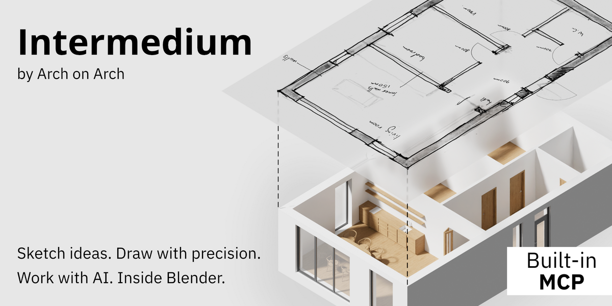
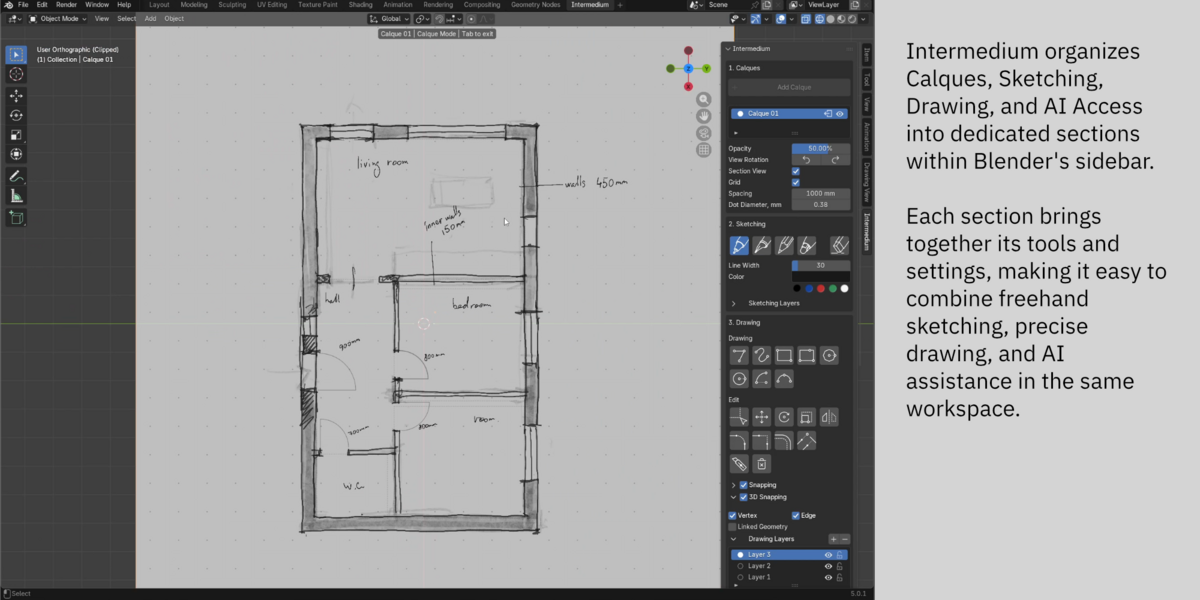
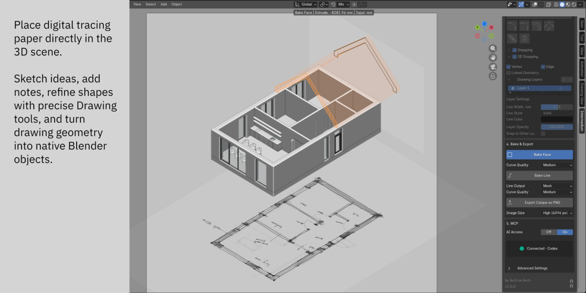
Intermedium brings together freehand Sketching, precise Drawing and a built-in MCP Gateway for working with ideas, 3D geometry and external AI agents inside Blender.
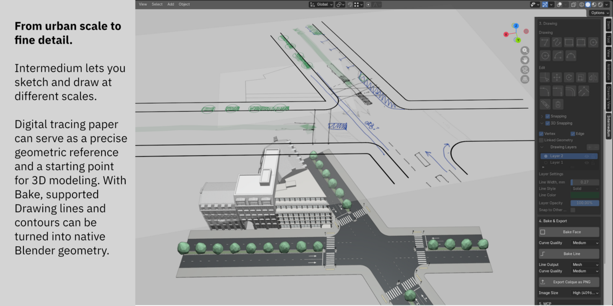
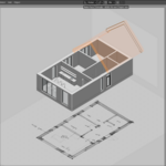
Calques are digital sheets of tracing paper in the 3D scene. Use Sketching and Drawing on a Calque, convert drawings into geometry with Bake, or work with an agent through AI Access. These tools can be used separately or together.
Contents
| 1. Installation and updating | 7. AI Access — connection and permissions |
| 2. Quick start | 8. Working with AI agents |
| 3. Calques and navigation | 9. Saving projects |
| 4. Sketching | 10. Troubleshooting |
| 5. Drawing | 11. Compatibility and scope |
| 6. Bake and export |
1. Installation and updating
1.1. Before installation
Download the Intermedium installation ZIP. Check the supported Blender versions in Compatibility (Section 11).
Sketching, Drawing and Bake work locally without an AI account. Sketching supports a pen tablet. AI interaction requires a separate compatible agent; no AI model is included.
1.2. Installing the add-on
- Download the ZIP from your Orders page on Superhive.
- Drag it into the Blender window and confirm installation, or use Blender’s Install from Disk command.
- Confirm that Intermedium is enabled.
- With the pointer in the 3D View, press N if the Sidebar is hidden, then select Intermedium.
1.3. Updating
Save your project before updating and keep a backup of important work.
Through Blender: if Superhive is connected as a Remote Repository, install the update directly through Blender.
From a ZIP: download the update from Orders. In Blender Preferences → Add-ons → Intermedium, click Update from ZIP and select the file. Drag-and-drop and Install from Disk also work. After any update, restart Blender, reopen the project and check its drawings. For AI work, use the existing connection as described in Reconnecting (Section 7.3).
Enable Creator Emails for update emails. News and previews are also shared on Arch on Arch’s Instagram and YouTube.
2. Quick start
2.1. Create a Calque and start drawing
- Open Intermedium in the 3D View Sidebar (N). In the Calques section, click Add Calque.
- Move the preview to the intended position and left-click to place it.
- With the Calque selected, press Tab to enter its working view.
- Choose Sketching for freehand work or Drawing for precise linework:
- Sketching: select a tool, adjust its settings, then press and drag to draw. Release to finish the stroke.
- Drawing: select Line / Polyline, Spline, Rectangle, N-gon, Circle or Arc. Click to place the first point, then define the remaining points and dimensions. See Drawing tools (Section 5.2) for each tool’s click sequence.
Continue drawing, or use the Bake & Export section:
| You want to… | Action |
|---|---|
| Create a face or volume | Click Bake Face, hover over a closed Drawing region, then click for a face or press and drag to extrude. |
| Create Mesh or Curve lines | Choose Line Output, click Bake Line, hover the connected Drawing chain and click. |
| Save a drawing image | Click Export Calque as PNG. Only visible Sketching and Drawing content is exported, on a white background without the model. |
Press Tab to leave the Calque. Bake also works from the normal 3D View with the source Calque visible. Save the Blender project to keep editable work.
2.2. Work with an AI agent
Open the MCP section, turn AI Access on and wait for Ready for AI.
For your first connection, click Copy MCP Settings and paste the message into a new chat in your AI client. Complete the short procedure in First-time setup (Section 7.2). For an existing connection, use Reconnecting (Section 7.3).
Once connected, give a task, for example:
Follow the instructions on Calque 03 and update the shape of the window opening.
3. Calques and navigation
3.1. Creating a Calque
- In the 3D View, open the Sidebar (N), select Intermedium and open the Calques section.
- Click Add Calque. A placement preview follows the pointer.
- Hover over model geometry to align the Calque to a surface, or press X, Y or Z for a world-axis orientation in free space.
- Left-click to place it. Esc or right-click cancels placement.
The new Calque is selected but not entered automatically.
3.2. Entering and exiting a Calque
Select the Calque’s frame in the 3D View or its row in the Calques list. With the pointer over the 3D View, press Tab to enter its orthographic working view. Press Tab again to exit.
3.3. Working outside a Calque
Select and rename: click a frame or list row to select a Calque. Edit its name in the list.
Move, rotate and scale: with the Calque selected, use G, R or S and confirm. These transforms affect the plane itself, not individual Drawing elements.
Visibility: use the eye icon beside a Calque, or the eye control above the list for all Calques. Outside its working view, the sheet has a fixed light appearance; adjustable Opacity is available inside.
3.4. Working inside a Calque
The Calques section provides the following working-view settings.
Opacity — adjust the sheet from 10% to 80% opacity. This is separate from Sketching and Drawing layer opacity.
View Rotation — use Left or Right to rotate the view by 90°, without changing the plane’s orientation in the scene. Finish the active drawing gesture first.
Section View
Position the Calque through the model, enter it with Tab, and use Section View in the Calques section. It is on by default for new Calques. Use Solid or Wireframe shading; turn Section View off to see the uncut model.
This is a display setting, not a cut in the model’s geometry. If Bake temporarily suspends the section, click Resume when shown.
Grid
Enable Grid to display a dotted grid; it is off by default. Adjust Spacing for the distance between points and Dot Diameter, mm for their displayed size. Initial spacing corresponds to one real metre at the scene’s unit scale.
To snap to it, also enable Grid in the Drawing section’s Snapping settings. The grid is not included in PNG export.
4. Sketching
4.1. Sketching tools
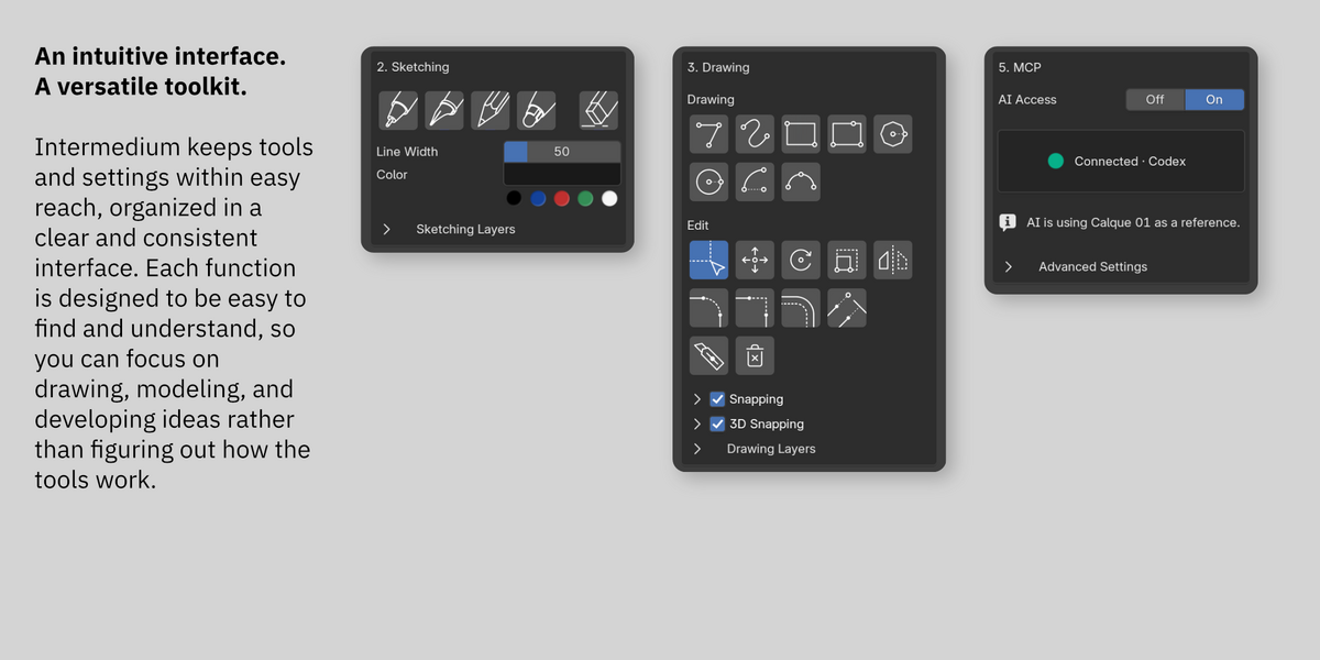
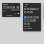
Enter a Calque and choose a tool in the Sketching section. The tiles appear in this order:
| Tool | Use |
|---|---|
| Liner | A clean ink-like line for outlines and detailed work. |
| Fountain Pen | An expressive ink-like stroke with width and tone variation. |
| Pencil | A graphite-style stroke for studies and detailed drawing. |
| Clutch Pencil | A broader, lighter graphite-style stroke. |
| Eraser | Removes marks from the active Sketching layer. |
4.2. Tool settings and strokes
Choose a tool and set Line Width and Color. For Pencil and Clutch Pencil, choose Strength: HB / 2B / 4B. Press and drag to draw; release to finish the stroke. Pen-tablet input is supported, with different responses for each instrument.
4.3. Eraser
Select the intended Sketching layer, choose Eraser, set Eraser Width and drag over unwanted marks. Eraser affects freehand strokes on that layer, not precise Drawing elements.
4.4. Sketching layers
Expand Sketching Layers and select the layer before drawing or erasing. Use + to add a layer, the eye icon for visibility, the lock for editing protection, and Layer Opacity for transparency. The minus control removes the layer; at least one layer remains.
To clear all strokes without deleting the layer: select and unlock it, then click Layer Settings → Clear Sketch. Other layers and Drawing content remain unchanged.
5. Drawing
Tools: Section 5.2 · Transforms: Section 5.4 · Snapping: Section 5.10 · Shortcuts: Section 5.12
5.1. The Drawing workspace
Drawing creates precise, editable 2D drawings on a Calque. Enter the Calque with Tab, open the Drawing section and select an editable Drawing layer. Use numerical input, snapping and direct editing to control shape and dimensions.
5.2. Drawing tools
Click a Tool Tile in the Drawing section, or press Shift+A over the 3D View with Drawing active to open Add Drawing. Hover a tile for its tooltip. The tools below follow the interface order.
Line / Polyline is one tool. Completion depends on the tool; double-click is not a universal finish command. See Esc and shortcuts (Section 5.12) for cancellation and completion rules.
5.2.1. Line / Polyline
- Select Line / Polyline, click the first point, move the pointer and click the next point.
- For an exact segment, type its length while positioning the endpoint, such as
1m, and press Enter to add it. - Continue placing points, or press Enter with no active numerical entry to finish. Click the first point again to close the path.
5.2.2. Spline
A Spline uses a control polygon, or cage, rather than standard Blender Bézier handles. The open curve meets its end controls; interior controls guide its shape without necessarily lying on the visible curve.
Create: select Spline and click at least three controls. While placing the next control, type a length and press Enter to set that cage edge’s length. Press Enter with no numerical entry to finish an open curve, or click the first control to close it. Backspace removes the last control when no numerical text is active.
Edit: choose Select, click the Spline and work with its cage on the active unlocked layer.
| Action | How |
|---|---|
| Move a control | Drag the control and release. |
| Add a control | Hover a cage edge until + appears. Click to insert, or press and drag to insert and position it. |
| Remove a control | Select it and press X / Delete. At least three controls must remain. Select the curve instead to delete the whole Spline. |
| Cut a cage edge | Alt-click the edge. An interior cut splits an open cage; an end-edge cut shortens it; a cut in a closed cage opens it. |
| Open or close | Use Open / Close in the contextual Spline row below Edit. When opening, a selected control sets the starting point. |
Adding, removing or cutting cage controls can change the curve’s shape.
Extend: select a free end of an open Spline, or hover near that end of the selected curve, and press E. Place the new control by clicking or entering a cage-edge length. Press E again for another extension; Esc or right-click cancels the current addition. The value measures the cage edge, not the visible curved span.
Connect ends: select both open Splines and drag one free end onto the other with Endpoint snapping. Bringing the two ends of the same Spline together can close it if enough distinct controls remain.
Limits: a closed or already connected end cannot be extended. J does not merge Splines. Regular Trim can trim the visible curve at supported intersections, but Alt+Trim cannot split it; use the cage cut instead. Bevel supports suitable open endpoints, not closed Splines. Extend to Corner can use a Spline as a fixed boundary.
5.2.3. 2-Point Rectangle
Select 2-Point Rectangle, click the first corner, then click the opposite corner. For exact dimensions, type width;height after the first point, for example 800mm;600mm, and press Enter. Position the pointer on the intended side before confirming. The sides follow the Calque’s working axes.
5.2.4. 3-Point Rectangle
Select 3-Point Rectangle and click the starting point. Click a second point to set the first side, or type its length and press Enter. Move perpendicular to that side and click the third point, or enter the width and press Enter.
5.2.5. N-gon
Select N-gon and click the centre. Move to set the outer radius; use the mouse wheel to change the number of sides. Click to confirm, or type a radius and press Enter.
5.2.6. Circle
Select Circle, click the centre and move outward to set the radius. Click to confirm, or type the radius and press Enter.
5.2.7. Radius Arc
Select Radius Arc and click the centre. Move to set the radius and starting direction, then click; you can enter the radius and press Enter at this stage. Move around the centre to choose the end angle and click to complete the arc.
5.2.8. 3-Point Arc
Select 3-Point Arc and click the start. Click the end to define the chord, or type its length and press Enter. Move perpendicular to the chord to choose the rise and side, then click or enter the rise and press Enter.
5.3. Selecting and direct editing
Choose Select, then click an element. Shift-click adds or removes elements; drag a box for a group. A selects all available elements; Alt+A deselects.
Drag an element’s points or controls to edit it. For Splines, selecting a control is different from selecting the whole curve; see Spline (Section 5.2.2).
5.4. Moving, rotating and scaling
Select the elements first. G / R / S starts a free transform; the Move / Rotate / Scale tile starts its reference-based version. Press B during a keyboard transform to switch to reference points.
Move
Free: press G, move the pointer and click or press Enter. X / Y locks a working axis; a typed value sets the distance.
Point-to-point: press G → B, or click Move. Click the base point, then the destination using snapping. Alternatively, type a distance along the chosen direction and press Enter.
Rotate
Free: press R, rotate around the selection centre with the pointer or enter an angle, then confirm.
Reference: press R → B, or click Rotate. Click the pivot, then a point defining the original direction. Click the new direction, or type a rotation angle and press Enter.
Scale
Free: press S, scale around the selection centre with the pointer or enter a factor, then confirm.
Reference: press S → B, or click Scale. Click the fixed point and a second point defining the original length. Click to set the new length, or type it and press Enter. This numerical value is a target length, not a scale factor.
Repeat a transform
Press Shift+R to repeat the last Move, Duplicate, Rotate, Scale or Mirror on the current selection in the same Calque and Drawing layer. For example, place a Shift+D duplicate, then repeat to make another copy at the same offset.
Reference rotations/scales retain their pivot; free versions use the current selection centre. Mirror retains its axis and copy choice. Finish the active gesture first. Creation tools, Trim and Bevel are not repeated.
5.5. Mirror
Select the elements and click Mirror or press Ctrl+M. Click two points to define the mirror axis. The second click creates a mirrored copy; hold Alt at that click to mirror the original instead.
5.6. Bevel and Extend to Corner
Bevel: select suitable corners or elements and click Bevel or press Ctrl+B. With no selection, start the tool and pick two curves. Move to choose the transition and radius; click to accept or enter a radius and press Enter. For Splines, only supported open endpoints can be used.
Extend to Corner: click the tile or press F, then pick two elements or use a compatible selected pair. Confirm the proposed intersection when a preview is shown. The tool extends or trims eligible elements to meet; a Circle or Spline used as a boundary stays fixed.
5.7. Offset and Extend
Offset: select an outline or chain and click Offset or press I, or start without a selection and pick the source. Move to choose the side and distance, then click or enter a distance and press Enter. Suitable Line/Arc/Spline chains and Circles are supported; branching chains are not. A fitted Spline offset may not maintain an exact constant distance everywhere.
Extend: click the tile or press E, click near a straight Line’s free end and choose the target or enter the extension value. A Spline may serve as a boundary; to extend a Spline itself, use its cage workflow (Section 5.2.2).
5.8. Trim, Split, Delete and Join
Trim: click the tile or press K, hover the interval to remove and click. Drag across several intervals to trim them together. Supported Lines, Arcs, Circles and Splines can be trimmed.
Split: with Trim active, Alt-click a supported Line or Arc to insert a vertex without removing the adjoining portions. The action returns to Select. There is no separate Split button; this does not split a visible Spline curve.
Delete: select elements and click Delete, or press X / Delete. A selected Spline control is removed instead of the whole curve, provided three controls remain.
Join: select at least two touching, compatible segments and press J; there is no Join tile. Join merges collinear Line chains or continuous Arcs on the same circle, not gaps, mixed Line/Arc selections or Splines.
5.9. Numerical input
Type values while the relevant preview is active, before confirming. The tool descriptions above identify the value at each stage. Lengths accept units such as 800mm or 1m; R takes an angle and free S a factor. Reference Scale takes a target length.
Line Width changes appearance, not drawing dimensions.
5.10. Snapping
5.10.1. Snapping on the Calque
In the Drawing section, enable Snapping and select: Endpoint, Midpoint, Center, Intersection, On Segment, Tangent, Quadrant, Extensions, Grid, Angles (0°, 30°, 45°, 60°, 90°), Parallel and Perpendicular. For grid snapping, also enable Grid in the Calques section.
5.10.2. 3D Snapping
Enable 3D Snapping and select Vertex and/or Edge. Enable Linked Geometry to include linked objects. Model references are projected onto the Calque plane; the drawing remains planar.
5.11. Drawing layers and appearance
Expand Drawing Layers, select the layer and use its visibility and lock controls. Adjust Line Width, Line Style, Line Color and Opacity. To copy selected elements to another Drawing layer in the same Calque, press Ctrl+C, make the target layer active, then press Ctrl+V. The copy is pasted in place.
5.12. Drawing shortcuts and commands
These keys apply with Drawing active inside a Calque and the pointer over the 3D View.
| Command | Shortcut or action |
|---|---|
| Select | Select tile; click, Shift-click or box select. A selects all; Alt+A deselects. |
| Add Drawing | Shift+A opens the drawing-tool menu. |
| Move / Rotate / Scale | G / R / S; then B for reference points. Their tiles start reference mode directly. |
| Mirror | Ctrl+M; Alt at the second axis click mirrors the original. |
| Bevel | Ctrl+B. |
| Extend to Corner / Offset / Extend | F / I / E. E extends the cage when a suitable Spline is selected. |
| Trim / Split | K starts Trim; Alt-click inside Trim performs Split. |
| Delete / Join | X / Delete removes the selection; J joins compatible Line or Arc chains. |
| Duplicate / Copy / Paste | Shift+D / Ctrl+C / Ctrl+V. |
| Repeat transform | Shift+R repeats the last supported transform. |
| Return to Select | Esc; see the unfinished-work rules below. |
Esc and unfinished work: Esc returns to Select. A Line / Polyline with at least two points or Spline with at least three controls is completed from those points. Right-click cancels the unfinished path instead. Unfinished Rectangles, N-gons, Circles and Arcs are cancelled. Unconfirmed transforms are cancelled; after Shift+D, only the move is cancelled and the duplicate stays at its original position.
During supported point placement, Shift locks direction and Alt temporarily allows free placement. Trim and Mirror use Alt as described above.
6. Bake and export
Bake converts Drawing into native Blender geometry; PNG saves an image. Bake Face and Bake Line work inside or outside a Calque. Keep the source Calque visible and use a single 3D View in Object Mode, not Quad View.
6.1. Choosing a Bake output
Use Bake Face for a face or extruded volume. Use Bake Line with Line Output: Mesh / Curve for line geometry. Both use Drawing elements, not freehand Sketching strokes.
6.2. Preparing contours
Bake Face needs an enclosed region. Check for gaps, duplicate segments or extra outlines. Hover before confirming: the highlight shows the region or connected chain to be baked, including the effect of nested loops and intersections. Bake Line accepts open or closed connected chains.
6.3. Bake Face
In the Bake & Export section, select Bake Face and hover over an enclosed Drawing region:
- Click to create a native mesh face.
- Press and drag to extrude the region along the Calque normal. Release to confirm the mouse-defined height, or type a height and press Enter.
The source drawing remains unchanged. Esc or right-click cancels an uncommitted action.
6.4. Bake Line
Set Line Output to Mesh or Curve, click Bake Line, hover the intended chain and click. Mesh creates edges; Curve creates native Curve geometry. The source drawing is retained.
6.5. Quality and later changes
Curve Quality controls approximation of curved outlines in Bake Face and has a separate setting for Bake Line’s Mesh output. Use the detail needed for the model.
Baked objects are independent: changing the drawing does not update them automatically. Edit or regenerate the result when needed.
6.6. PNG export
Select or enter the Calque. In Bake & Export, choose Image Size: Standard (2048 px), High (4096 px) or Ultra (8192 px), then click Export Calque as PNG and choose a filename and location. The size sets the image’s long edge; proportions follow the sheet.
PNG export includes only visible Sketching and Drawing content on a white background, without the 3D model or other viewport elements.
7. AI Access — connection and permissions
First-time setup: Section 7.2 · Reconnecting: Section 7.3 · Connection problems: Section 10.2
7.1. Understanding AI Access
Intermedium provides its own MCP Gateway, Blender tools and guidance. Use a compatible AI client such as Codex or Claude Code with access to the computer running Blender. No additional Blender MCP add-on is required. Intermedium does not include an AI model.
AI Access allows the connected agent to read scene data and Calque images and modify the scene through supported tools. Requested data may be sent to the agent’s AI provider. The provider’s terms, privacy policy and usage costs apply separately.
The MCP connection settings include a unique access key for connecting your AI client to Intermedium.
Gateway lifetime: AI Access starts a local gateway process. When no Blender instance has AI Access enabled, the gateway shuts down automatically after about 120 seconds.
On Windows, gateway files, connection keys, settings and configuration backups are stored in %LOCALAPPDATA%\Intermedium. Saved user instructions and project-instruction approvals use a separate folder, %APPDATA%\Intermedium. These folders and temporary caches may remain after uninstalling Intermedium. See Local data and complete removal (Section 11.3).
7.2. First-time setup — cold connection
Follow these steps the first time you connect a particular AI client or profile.
-
Open the MCP section. Open your project in Blender. In the 3D View Sidebar (N), select Intermedium and open the MCP section.
-
Enable AI Access. Set AI Access to On and wait for Ready for AI. Intermedium is ready to accept a connection, and Copy MCP Settings appears below the switch.
-
Connect your AI client. Click Copy MCP Settings, open a new chat in your AI client and paste the complete copied message. Let the agent proceed with setup. Review its proposed actions and permission requests before approving them, making sure they relate to connecting Intermedium.
-
Check the connection and start working. Once setup is complete, open a new chat in your AI client if needed and ask the agent to connect. For example:
Connect to Intermedium in Blender and check that its tools are available.
When the agent confirms the connection and the MCP section in Blender shows Connected, you can start working with the scene.
After the first successful connection, Copy MCP Settings and How to Connect move into Advanced Settings.
7.3. Reconnecting — warm connection
-
Open your Blender project. In the MCP section, turn AI Access on if needed and wait for Intermedium to become ready.
-
In the AI client and profile you previously connected, ask the agent to reconnect. For example:
Connect to Intermedium.
-
Once the agent confirms the connection and Blender shows Connected, give your task.
You can normally use the same chat. There is no need to copy the settings again or reconnect for each task. After the gateway restarts, use your client’s reconnect action if needed; the existing registration can be reused. If the connection address changes, follow Section 10.2.
Intermedium can repair its own recognized existing user-level MCP entries in Codex and Claude Code. It backs up the configuration before making changes. New registrations must be set up by you or your agent. Project-scoped registrations and other clients’ configurations are not edited automatically. Backups are stored in mcp/config_backups/ inside the Intermedium data folder and may contain client credentials.
7.4. Other clients and connection controls
| Situation | Action |
|---|---|
| Connect a different AI client or profile | Open Advanced Settings → Copy MCP Settings and follow first-time setup in that client. |
| Intermedium shows Repair Connection | Click it, wait for readiness and repeat the connection check. |
| Intermedium shows Another Blender is selected | In the intended Blender instance, enable AI Access and open Advanced Settings → Route Clients to This Blender. Confirm, then ask the agent to reconnect in the same chat and refresh its scene context. |
For missing tools, changed addresses or setup errors, see Connection troubleshooting (Section 10.2).
7.5. What the agent can do
Supported tasks include scene inspection, mesh and curve modeling, text, collections, modifiers, Geometry Nodes, materials, shader nodes, cameras, lighting and library resources. Ask for the result you need; the agent can consult Intermedium’s operations and guidance to carry it out.
Available operations depend on the installed version and the objects involved. Review important dimensions and the resulting model before continuing.
7.6. Access controls and Python Access
Set AI Access to Off in the MCP section to close access and cancel queued work. This does not undo completed changes or necessarily stop a Blender operation already running.
Python Access is optional and off by default. Standard Intermedium operations do not require it. For a task that needs arbitrary Python:
- With AI Access on, open Blender Preferences → Add-ons → Intermedium and find Python Access.
- Click Enable Python Access, read the warning, tick the acknowledgement and confirm the dialog. Use the control again to disable it.
The Python tool remains visible while access is off, but cannot execute. Enabling Python Access requires your confirmation in Blender. After confirmation, continue in the same chat without reconnecting. Permission applies to all current and future clients of that AI session and resets when the session, authorized window, scene or view layer changes.
Python execution is not sandboxed: it may modify the scene, access local files and perform system actions with Blender’s permissions. This is broader access than the standard tool catalog.
Disabling Python Access blocks new Python requests but does not stop code already running or undo its changes.
8. Working with AI agents
8.1. Built-in instructions and guidance
Intermedium provides more than access to tools. It also helps agents understand how to use them effectively.
Intermedium includes built-in guidance to help AI agents use its modeling tools. Some task-specific guidance covers selected architectural workflows, but it does not limit the types of projects you can work on.
8.2. Communicating through Sketching
A sketch can express an early idea or a detailed technical solution. Name the Calque and explain which marks describe the proposed change.
Use the sketch on Calque 03 to understand the proposed handle shape. The surrounding drawing is reference context. Describe your interpretation before making changes.
Sketching is shared with the agent as an image, not as exact stroke coordinates. Interpretation depends on the agent and the clarity of the reference.
8.3. Communicating through Drawing
Drawing supplies exact geometric references. Identify the Calque and contour, then state any missing information such as depth, material or what must remain unchanged.
Use the closed Drawing contour on Calque 03 as the profile. Keep its in-plane dimensions unchanged and create a form 0.20 m deep. Keep the reference object unchanged.
8.4. Continuing and checking work
References are kept for the current task. Exiting a Calque, orbiting the view or selecting another sheet does not retarget that task. To use a different drawing, give a new instruction naming it. The MCP section shows the task’s Calque references when available.
Check dimensions, form and editable geometry after important changes. If Blender shows AI work waiting, finish the active editing gesture and let the agent continue. Cancel removes queued work; it does not undo completed changes or necessarily interrupt a running operation.
You can provide additional project requirements directly in the AI conversation or through your own Markdown files, using the file features supported by your AI client.
9. Saving projects
Calques, including their Sketching and Drawing content, are stored in the Blender project file (.blend) and saved together with the scene.
10. Troubleshooting
10.1. Drawing, Calques and Bake
| Problem | What to check |
|---|---|
| Sketching or Drawing is unavailable | Enter the intended Calque with Tab. Select a visible, unlocked layer in the appropriate section. |
| A mark cannot be erased or selected | Use Eraser for Sketching, Select/Delete for Drawing, and Blender’s own tools for baked objects. Check the active layer and Calque. |
| Snapping chooses the wrong reference | Reduce competing snap options or hide unrelated references; check the snap feedback before clicking. |
| Bake Face gives the wrong region | Check the Drawing contour for gaps, duplicate segments or extra outlines. Use the highlighted region to confirm the source; Sketching strokes are not Bake contours. |
| Section View is missing | Check that the plane crosses the model, enter the Calque and enable Section View in Solid/Wireframe. Use Resume if shown. |
| PNG differs from the viewport | PNG exports only visible Sketching and Drawing content on a white background, without the 3D model or other viewport elements. Check Image Size and layer visibility. |
10.2. Connection and agent tasks
| Problem | What to do |
|---|---|
| Copy MCP Settings is missing | Expand Advanced Settings in the MCP section. If unavailable, turn AI Access on and wait for readiness. |
| Ready for AI, but no tools | For a new client, follow Section 7.2. Otherwise refresh the client’s tools or open a new chat and ask it to connect to Intermedium. |
| The agent reports Registered; verification pending | Open a new chat in the same AI client and profile, then ask it to connect to Intermedium. Restart the application only if the client requires it. |
| Tools are missing in a different AI-client project | Check whether the MCP connection was registered only for the original project folder. If so, use that folder or ask the agent to explain how to make the connection available in the new project. |
| Client permissions prevent setup | Review the proposed setup action and the requested access. Approve only a change you understand that is needed for connecting Intermedium, or complete the client’s supported manual setup. |
| The saved connection no longer works | Use Repair Connection if shown. If an existing Codex or Claude Code registration was repaired automatically, open a new chat in the same AI client and profile and ask it to connect. If the connection still fails, copy the current settings and ask the agent to update the existing registration. Resolve any conflict or permission request it reports. |
| Connected to the wrong Blender | In the intended Blender instance, enable AI Access and open Advanced Settings → Route Clients to This Blender. Confirm, then ask the agent to reconnect in the same chat and refresh its scene context. |
| An operation is rejected | Read the error and ask the agent to correct the target, parameters or permissions. Enabling Python Access is not a general fix. |
| The agent uses the wrong drawing | Name the intended Calque and give a new task. Ask the agent to describe its reference before editing. |
| Work is waiting | Finish the current Blender gesture. Use Cancel beside AI work waiting to remove queued work. |
| The result misses the intent | Identify the specific shape, dimension or placement to correct, then review that correction before continuing. |
A cloud-only client without access to the computer running Blender cannot reach the local connection.
11. Compatibility and scope
11.1. Blender and operating systems
Minimum Blender version: 5.0.1. Tested versions: 5.0.1, 5.1.0 and 5.2.0.
Supported platform: Windows.
11.2. AI clients and results
Recommended AI agents: Codex and Claude Code. Both have been tested with Intermedium for MCP connection and modeling workflows. Compatibility with other AI agents has not been verified.
Sketching, Drawing and Bake remain usable without AI. Agent interpretation and design decisions still require your review; the supported operation catalog does not cover every Blender action.
11.3. Local data and complete removal
To remove Intermedium and its auxiliary data completely on Windows:
- Save your projects, turn AI Access off in every Blender instance and uninstall Intermedium through Blender’s Extensions or Add-ons preferences.
- Close the AI apps you used with Intermedium and close Blender.
- Wait at least 120 seconds for the gateway to exit. Open File Explorer, paste
%LOCALAPPDATA%\Intermediuminto the address bar at the top and press Enter. Delete that folder once no other Intermedium installation is using it. This removes connection keys and configuration backups; reinstalling will require a new connection. - In File Explorer, paste
%APPDATA%\Intermediuminto the address bar and press Enter. Delete that folder if it exists. This resets your saved instruction preferences and project-instruction approvals. - In File Explorer, paste
%TEMP%into the address bar at the top and press Enter. Windows opens your temporary folder automatically. Removeintermedium_raster_cache_v2and any leftoverintermedium-cache-worker-*orintermedium-render-*folders after their processes have exited.
Optionally, remove the Intermedium connection from your AI app if you no longer plan to use it.
Your saved .blend projects and exported images remain intact.
Intermedium 1.0.0 — User Guide.
 Included
Includes 12 months of
- Support from Arch on Arch
- Product updates
Extend this product’s Support Period +12 months: 50% of product price
Have questions before purchasing?
Login to message
| Blender Extension Compatible | Yes |
| Published | 1 day ago |
| Blender Version | 5.0 - 5.2 |
| Extension Type | Add-on |
| License | GPL |
Discover more products like this
3d modeling tracing paper Geometry 3D sketching MCP precision drawing cad AI agents concept-design Design Workflow sketching drawing