Oh My Gear 2 - Geometry Nodes Gear Generator
 DrBlender





Library version 2.0.5 · Blender 5.2 LTS and 4.5 LTS
This is the whole guide, for both packages, in one place. Everything in it is inComplete. The few things that are not in Core are markedComplete; if you own Core and a heading says that, you can skip it.
Two other files are in the download and this guide does not repeat them:ASSET_CATALOG.md lists every input of every group with its default and range,and MECHANICAL_CONVENTIONS.md has every equation and sign convention.
1. Install
There is nothing to install. This is a .blend file, not an add-on.
Either open the file that matches your Blender and work in it,
or — better — register the folder once so everything follows you into everyproject:
- Edit → Preferences → File Paths → Asset Libraries
-
+, point it at the folder holding the
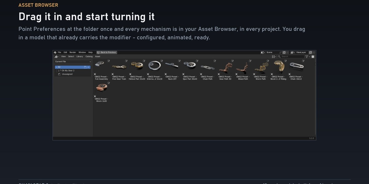
.blendandblender_assets.cats.txt, name itOh My Gear 2 - Open an Asset Browser and choose that library. You will see:
Oh My Gear 2├── Basic plain gears, pairs and trains├── Extended worm, chain, bevel (Complete)├── Assemblies the stacked controller (Complete)├── Curve Paths the four curve systems (Complete)└── Materials nineteen procedural finishes.blend saved by Blender 5.2 cannot be opened by 4.5, so thedownload holds one file for each. Open the one that matches your Blender. Theycontain the same library.Materials are in the same browser. Drag one onto any object.
2. Your first gears in one minute
- Add any mesh object. A default cube is fine — its geometry is discarded.
- Add a Geometry Nodes modifier.
- Click the browse icon and pick
OMG2_Mesh_Pairing. - Set
Teeth AandTeeth B. - Click the
Drivefield, type#frame/96and press Enter.
Press play. The second gear is placed at the solved centre distance, phased soits teeth fall into the gaps of the first, and counter-rotated at the correctratio. You changed two numbers.
3. The conventions you need
Everything in the library follows these. Learn them once.
Drive is in turns |
Drive = 1.0 is one full revolution, counter-clockwise about +Z. Not radians, not degrees. |
Phase is in tooth pitches |
Phase = 1.0 shifts the gear by exactly one tooth. Not radians. |
Module is pitch diameter ÷ tooth count |
In scene units. Two gears mesh only if they share a module. |
| Everything is +Z | Gears lie in the XY plane and turn about Z. On a curve, the first gears are drawn in Top view. |
Lengths follow scene units. At the default Unit Scale, 1 unit = 1 m.
4. Which group do I use
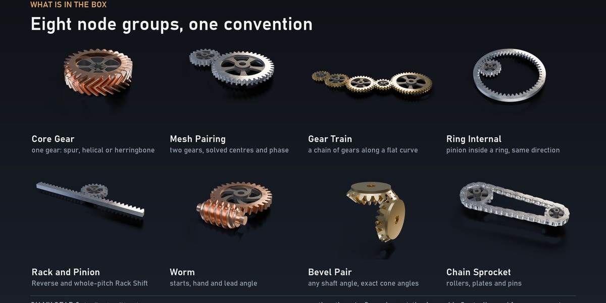
| You want | Use | Package |
|---|---|---|
| One gear | OMG2_Core_Gear |
Core |
| Two gears that mesh |
OMG2_Mesh_Pairing (turn on Internal and B becomes a ring) |
Core |
| A train of gears along a flat curve | OMG2_Gear_Train |
Core |
| The solved layout of a train, without building it | OMG2_Curve_Layout |
Core |
| A pinion running inside a ring gear | OMG2_Ring_Internal |
Complete |
| A rack driven by a pinion | OMG2_Rack_and_Pinion |
Complete |
| A worm driving a wheel | OMG2_Worm |
Complete |
| Two sprockets and a roller chain | OMG2_Chain_Sprocket |
Complete |
| Two bevel gears on intersecting axes | OMG2_Bevel_Pair |
Complete |
| A worm, a spur pair and a rack stacked on shared shafts | OMG2_Assembly_Controller |
Complete |
| A mechanism you draw with a curve in 3D | OMG2_Gear_Path |
Complete |
| …the same, with roller chains on long runs | OMG2_Chain_Path |
Complete |
| …the same, with worm turns | OMG2_Worm_Path |
Complete |
| …everything at once, plus a worm motor and a rack or ring at the end | OMG2_Mixed_Path |
Complete |
Groups prefixed OMG2__ (double underscore) are internal helpers. Theirinterfaces are not part of the public contract — do not build on them.
Helical and herringbone are not separate groups. Helix Angle andHerringbone are inputs. In a pair or a train, setting Helix Angle gives eachneighbour the opposite hand automatically, so every mesh stays valid.
5. What each value controls
Every group arranges its inputs into the same named panels, so the panel a valuesits in tells you what it can change. If a value is in Body or Appearance, itcannot change the motion, the ratio or the centre distance.
| Panel | What it affects | What it cannot affect |
|---|---|---|
| Input |
Drive: what turns the mechanism |
|
| Gear Geometry | The numbers that define the gears: tooth counts, Module, the wall of a ring |
|
| Layout | Where parts sit relative to each other: Module and Min Teeth on a curve, rack side and shift, centre distance |
|
| Meshing | Tooth shape and engagement: Pressure Angle, Tooth Height, Backlash, Root Fillet
|
|
| Body | The disc behind the teeth: rim thickness, hub, bore, web, spokes, windows | The tooth profile, the ratio, the motion |
| Helical | Twist across the face width. Helix Angle 0 is a spur gear |
|
| Appearance | Materials only | All geometry |
| Quality | Mesh density and shading | The mechanics (only how smoothly it is drawn) |
| Turns, Worms, Chains, Ends | The curve systems' bevel turns, worm stages, chain runs and end parts Complete |
The values that do the real work
| Value | What it does | Watch out for |
|---|---|---|
Teeth (A / B) |
Sets the ratio. Ratio = Teeth A ÷ Teeth B, sign flips per mesh | Whole numbers only |
Module |
Sets the size of everything: pitch radius = Module × Teeth ÷ 2 | Gears that mesh must share it. On a curve, 0 means "work it out for me" |
Min Teeth |
On a curve with Module 0: the smallest gear gets exactly this many teeth, which fixes the module and so the size of every gear |
Raising it makes every gear smaller |
Pressure Angle |
Tooth flank steepness. 20° is the standard | Must match between meshing gears |
Tooth Height |
Addendum, as a multiple of Module | Must match between meshing gears |
Backlash |
Play between teeth, removed from tooth thickness |
0 is a zero-clearance mesh. The default 0.002 is what the materials are tuned around |
Phase / Phase Offset
|
Rotates one gear relative to its partner, in tooth pitches | Whole numbers change nothing visible, since every tooth looks the same |
Helix Angle |
Twists the teeth. Positive and negative are opposite hands | −45° … 45° |
Thickness |
Face width of the toothed rim | Hub and web are sized from it |
Bore Diameter |
Fixes the hole size in scene units. 0 uses Bore Ratio
|
Use it when several gears share one shaft |
Drive |
Turns the whole mechanism, in turns | See §6 |
Input Index |
Which gear of a train receives Drive directly |
The rest follow |
6. Animating
Everything turns from Drive alone, in turns.
-
Driver (recommended): click the
Drivefield, type#frame/48, press Enter. One full turn every 48 frames.#frame/-48runs backwards. - Keyframes: hover the field and press I on two frames.
Drive. Every other gear is geared to it and follows byitself, at the right ratio and the right phase. Keyframing a second gear'srotation will fight the solver.To chain groups, feed one group's Out Drive output into the next group'sDrive.
7. Gear trains on a flat curve
Put OMG2_Gear_Train on a curve object. Each curve point becomes a gearcentre. The modifier has to be on the curve itself.
Module at 0. The train then derives the module from the curve, sizingthe smallest gear to Min Teeth. This always solves: the curve sets the scale,so there is no configuration that fails.Set Module yourself only when the train has to mesh with parts you havealready fixed at a module. Then the curve has to be long enough — see the rulein §13.
Input Index picks which gear receives Drive directly.
Draw the curve as a Poly spline
Every curve group (Gear_Train, Curve_Layout and the four paths) puts a gearon every evaluated point of the curve, not on every control point. A Poly spline evaluates to its own points, so a Polyspline with five points gives five gears. A Bezier or NURBS splineevaluates to many points along the smooth curve between its control points: threeBezier control points at the default resolution gave 25 gears with a tinymodule in testing.
Do one of these:
- Convert to Poly. In Edit Mode, select the points, press F3, search Set Spline Type and choose Poly. Best option.
- Or keep a Bezier and set Resolution Preview U to 1 (Curve data properties → Shape). Then it evaluates to its control points, joined by straight segments. Leave the render resolution at 0 so the render matches the viewport.
NURBS does not reliably give one gear per control point, even at resolution 1.Use Poly.
The ready models in the Asset Browser are already Poly curves.
8. Curve paths — drawing a mechanism Complete
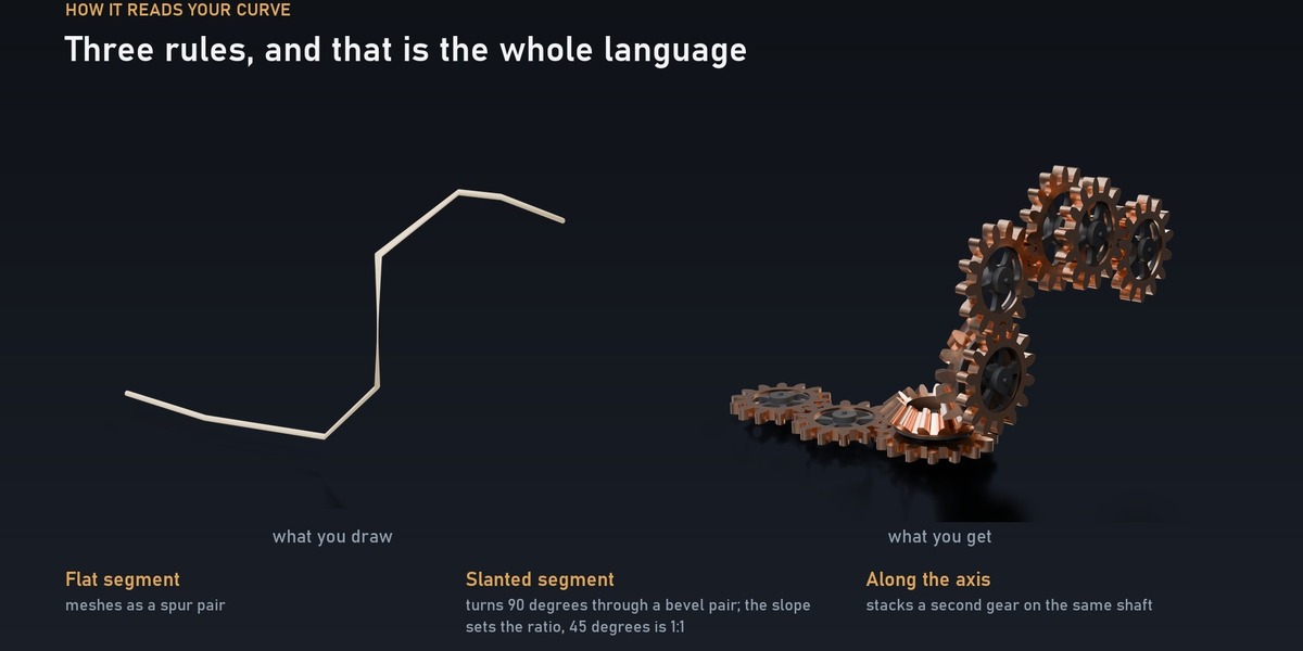
Put OMG2_Gear_Path on a curve object and draw the mechanism with thecurve's points. Every point is a shaft. Each segment between two points isread against the axis the path is currently on, and becomes one of three things:
| The segment… | Becomes | Where to read more |
|---|---|---|
| lies in the gear plane | a spur mesh, solved exactly like a flat train | §7 |
| leaves the plane at an angle | a 90° turn through a bevel pair; the path carries on in the new plane | below |
| runs along the axis | a second gear on the same shaft (a compound gear) | below |
The first gears are always in the XY plane, axis +Z. So: draw the firstfew points in Top view, keep them at the same height, and leave the plane onlywhere you want a turn.
How the angle of a segment decides what it becomes
"Lean" is how far a segment leaves the plane the path is currently on. TurnTolerance (default 6°) is how forgiving the solver is.
| Lean | What it becomes |
|---|---|
0° up to Turn Tolerance |
Flat. A spur mesh. A slightly sloping hand-drawn run is treated as level |
Turn Tolerance up to 90° − Turn Tolerance |
A 90° turn. The path continues in the new plane |
within Turn Tolerance of 90° |
Along the axis. A second gear on the same shaft |
The slope sets the ratio. The ratio of the bevel pair at a turn is1 ÷ tan(lean). 45° is exactly 1:1; steeper makes the gear after the turnslower, shallower makes it faster. Measured on a real path:
| Lean | Ratio across the turn (approx.) | What it looks like |
|---|---|---|
| 6° | × 9.3 | Enormous bevel driving a tiny one. Usually not what you meant |
| 15° | × 3.7 | Big ratio change; the turn parts are large |
| 30° | × 1.7 | Clear step-up |
| 45° | × 1.0 | 1:1. The natural choice |
| 60° | × 0.6 | Clear step-down |
| 80° | × 0.18 | Big step-down |
| 90° | — | Not a turn: a second gear on the same shaft |
Tooth counts are whole numbers, so the solver rounds: the real ratio is close tothe table, not exactly on it.
Turn Tolerance — the one that surprises people
Turn Tolerance (up to 40°)so that a gentle slope is treated as flat.It works both ways: with a tolerance of 20°, a 10° lean became flat in testing.
What the values in the Turns panel do
| Value | Does |
|---|---|
Turn Tolerance |
How far a segment may lean and still count as flat, and how close to the axis it must be to count as a shared shaft. Everything between is a turn |
Turn Gap |
Clearance along the shaft between a gear's hub and the turn part that shares the shaft. Too small and the hub hits the bevel — with Turn Gap 0 the parts collided in testing, at 1.0 they were clear. Default 0.05 |
Bevel Face Width |
Bevel tooth length as a fraction of the cone distance (0.05 … 0.5) |
Back Thickness |
The plate behind each bevel gear |
Worm Turns |
Mixed Path only. Off: slanted segments turn through bevel gears. On: through a worm and its wheel |
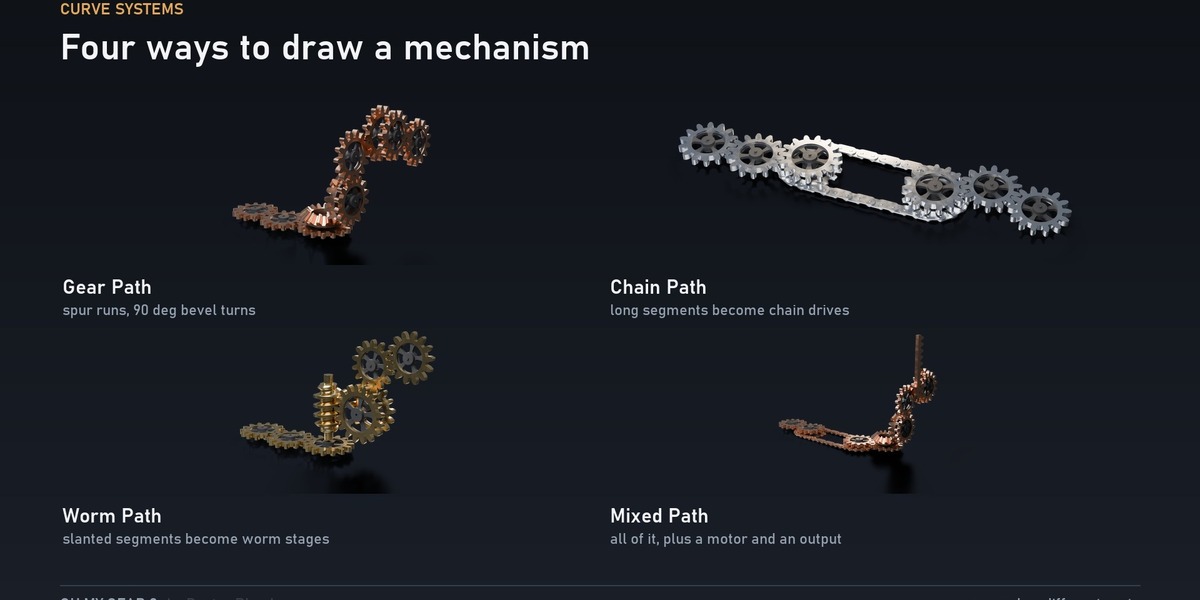
The four systems
They share one solver and one set of rules. What you learn on one works on all.
| Group | Flat segment | Slanted segment | Extra |
|---|---|---|---|
OMG2_Gear_Path |
spur mesh | 90° bevel pair | |
OMG2_Chain_Path |
spur mesh, or a roller chain when longer than Chain Distance
|
treated as flat | Flip Chains |
OMG2_Worm_Path |
spur mesh | worm on this shaft, wheel on the next; the path continues upright through the segment |
Worm Starts, Worm Diameter, Worm Length, Left Handed
|
OMG2_Mixed_Path |
spur or chain | bevel or worm (Worm Turns) |
Start: a worm motor under the first shaft. End: a rack, or a ring gear, on the last |
Chains. A flat segment longer than Chain Distance becomes a chain drivebetween two sprockets instead of a gear mesh. 0 never uses a chain. Sprocketsare Sprocket A Teeth (driving) and Sprocket B Teeth (driven); their ratio isthe chain's ratio. Chain Pitch 0 means "π × Module", so the sprockets are thesize of gears. The chain runs under the gears and consecutive chains alternatesides — if one hits something, turn on Flip Chains.
Worms. The ratio of a worm turn is Worm Starts ÷ wheel teeth. WormDiameter is the worm's pitch diameter in modules (5 … 20): bigger is afatter worm and a smaller wheel. Left Handed turns every worm stage the otherway.
Ends (Mixed Path). Start = 1 adds a worm motor under the first shaft,driving it through a wheel of Start Wheel Teeth.End = 1 adds a rack, End = 2 a ring gear with the last pinion inside it.End Teeth is the pinion on the last shaft; Rack Teeth and Ring Teeth sizethe part it drives. Ring Teeth must exceed End Teeth.
Outputs worth reading
Gear Count, Turn Count and Chain Count tell you what the solver decided.If you expected a turn and Turn Count is 0, the segment was inside thetolerance and got treated as flat. Total Ratio is the overall ratio; Moduleis the solved module, which you must feed to anything else meant to mesh withthe path.
Drawing tips
- Start in Top view. Draw the first three or four points flat.
- Turn once, then carry on. One point up and sideways makes the turn; draw the following points in the new plane.
- Leave room. Every turn needs a flat run before it long enough for the hub, the gap and the bevel. A very short run before a turn is where overlaps start.
- Move a point and the whole path re-solves. Tooth counts are integers, so as you drag, the counts step; the mesh is exact at every position you stop at.
-
Leave
Moduleat 0 until you need to fix it.
9. The other mechanisms Complete
OMG2_Ring_Internal — pinion inside a ring
The ring sits at the origin with the pinion inside it; both turn the sameway. Ring Teeth must be greater than Pinion Teeth, otherwise the groupis invalid and returns nothing. Rim Width is the wall of the ring outside theroot circle.
OMG2_Mesh_Pairing does the same with Internal switched on. There, Teeth Bis the ring, and it must also exceed Teeth A.
OMG2_Rack_and_Pinion
One pinion turn moves the rack one pitch circumference; Travel and RackPosition tell you where it has got to.
| Value | Does |
|---|---|
Rack Side |
Which side of the pinion the rack sits on (-Y or +Y). The contact side decides which way the rack runs for a given Drive direction |
Reverse |
Runs the rack the other way without moving it to the other side — it drives the pinion backwards. Use it to reverse one rack inside an assembly that shares a single Drive
|
Rack Shift |
Moves the rack along X by whole tooth pitches. Whole pitches keep the mesh exact; any other offset would break it |
Rack Teeth, Rack Depth
|
Length of the rack and depth of its body |
OMG2_Worm — worm and wheel
The worm lies along +X and drives a wheel on +Z. Ratio = Starts ÷ WheelTeeth (the sign follows the hand). Diameter Factor (q) is the worm's pitchdiameter divided by the module; Worm Length is in axial pitches; LeftHanded reverses the thread. The group reports Lead Angle: a single-start wormat the default q of 10 is about 5.7°; six starts at q 10 is about 31°.
OMG2_Chain_Sprocket — chain drive
Two sprockets and a closed roller chain. Center Distance is a request: thechain has a whole number of links (always even), so the solved distance isslightly different and is reported as Solved Center Distance (a request of 3solved to about 3.09 in testing). A request smaller than the two sprocketsneed is rejected, not silently enlarged.
| Value | Does |
|---|---|
Chain Pitch |
Roller pitch |
Chain Style |
0: simple bars, lightest. 1: roller chain with plates, rollers and pins |
Roller Diameter, Plate Height, Plate Thickness
|
As a fraction of Chain Pitch
|
Chain Width |
Inner width between the plates, as a fraction of pitch. Keep it wider than the sprocket Thickness or the plates cut into the sprockets |
Chain Phase |
Slides the chain along its loop in links, without turning the sprockets. Fine-tunes where rollers sit in the tooth gaps |
Chain Offset |
Moves the chain along the sprocket axes, to line it up with other parts |
Own Chain Material |
On: the chain uses Chain Material instead of Material
|
OMG2_Bevel_Pair
Two bevel gears on intersecting axes. Shaft Angle is the angle between the axes(10° … 170°); the cone angles are solved from it and the tooth counts.
Apex At Origin puts the shared cone apex at the origin. At small shaftangles the apex is far from the gears: at 10° the pair ended up about 11.6units from the origin with it on, against about 4.3 with it off. Leave it offunless you need the apex for alignment.
OMG2_Assembly_Controller
A worm, a spur pair and a rack stacked on shared shafts: the worm wheel and spurA are one shaft, spur B and the rack pinion the next, so each stage genuinelydrives the one below. One Drive runs all three and Total Ratio is the productof the stages.
| Value | Does |
|---|---|
Stage Gap |
Axial distance between stacked stages. Keep it above Hub Thickness or the hubs collide
|
Stage Angle |
Direction from the wheel shaft to gear B's shaft, measured from +X |
Rack Angle |
Direction the rack runs in, measured from +X |
Rack Side |
Which side of the pinion the rack runs on |
10. Body styles
Body Style changes only the look of the web. The toothed rim, the pitch radiusand the ratio are untouched.
| Value | Body |
|---|---|
| 0 | Round holes |
| 1 | Sculpted spokes |
| 2 | Curved spokes |
| 3 | Radial slots |
| 4 | Solid web |
Shaping inputs: Spokes (count — 0 always gives a solid web), Spoke Width(how much of each sector is material), Spoke Curve (bend; the sign mirrors thesweep), Window Shape (low is square-cornered, 1.0 is round).
Bore Diameter above zero fixes the hole size in scene units — use it whenseveral gears run on one shaft. At zero, Bore Ratio scales the hole with thegear. Hub Ratio, Hub Thickness and Web Ratio size the hub and the web.
11. Materials
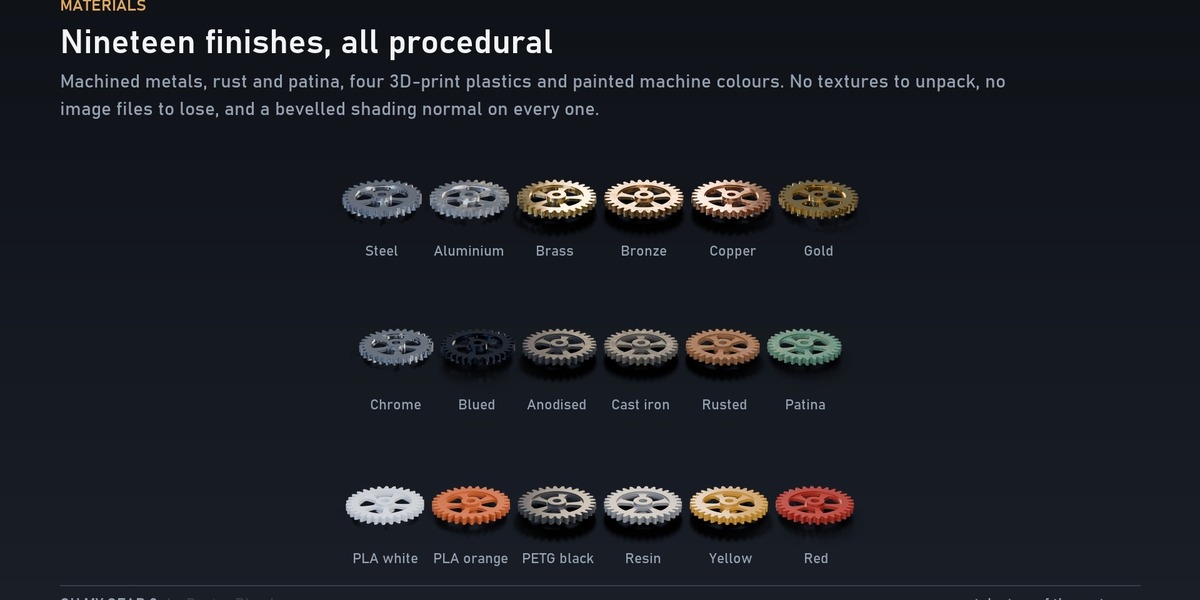
Nineteen procedural materials, no textures to unpack and nothing to lose. Findthem in the Asset Browser under Oh My Gear 2 → Materials, each with a renderedthumbnail and a one-line description. Drag one onto any object.
| Group | Materials |
|---|---|
| Machined |
Steel Aluminium Brass Bronze Copper Gold Chrome
|
| Finished |
Blued_Steel Dark_Anodised Cast_Iron
|
| Corroded |
Rusted_Steel Patina_Brass
|
| 3D print |
PLA_White PLA_Orange PETG_Black Resin_Grey
|
| Painted |
Painted_Yellow Painted_Red
|
All are named OMG2_MAT_*. They are also in the material dropdown of everyobject in the file, because each carries a fake user and survives a save whetheror not anything is using it.
Putting one on a gear. The gear's material is an input of the modifier,not a slot on the object. Put it in Material (the toothed rim). Turn on TwoMaterials and Body Material takes the hub, the web and the spokes.Dark_Anodised is the one to reach for on the body: it stays dark under stronglights instead of washing out to grey.
What is in them. Every material bevels the shading normal, so tooth tips andwindow edges catch a thin machined highlight instead of ending in amathematically sharp line. The metals carry two scales of roughness variation:a broad one at about the size of the part, and a fine grain on top. The printmaterials band along the part's own height at a real layer pitch — PLA_Whiteis a 0.05 unit layer — with a slow wobble, because a printer does not lay aperfect stack.
Retuning them. Every finish is an ordinary node tree in the file. Open it inthe Shading workspace and change whatever you like; a material you edit is yours.
12. Quality and speed
Points Per Tooth is the only quality control you normally touch.
| Value | Use |
|---|---|
| 6 | Draft: scrubbing a dense train |
| 10 | The default |
| 16+ | Final: renders and close-ups |
It is the main cost of every gear: halve it before anything else when theviewport is slow. Body Resolution (24 draft, 32 default, 64 close-up) sets howround the rim edge, hub, bore, holes and windows are.
Smooth Angle (default 50°) decides which edges stay sharp: edges bent furtherthan this stay sharp, flatter ones shade smooth. 30–60° suits gears; 180°smooths everything, which makes tooth flanks look soft.
A twenty-five gear train re-evaluates in well under a millisecond at the defaultquality.
13. What can break, and how to fix it
Find your symptom on the left. Where a group can tell you the cause itself, readits Valid and Warning Code outputs (§14).
Nothing appears
| Symptom | Cause | Fix |
|---|---|---|
| A curve group shows nothing | The modifier is on a mesh, not a curve. A curve group needs a curve object | Put the modifier on the curve itself |
| A curve group shows nothing | The curve has fewer than two points | Add a second point |
A path or train vanishes after you set Module
|
With a fixed Module, every flat segment must be at least 0.9 × Module × Min Teeth long to fit two gears. A shorter one makes the whole layout invalid, and it returns nothing |
Set Module back to 0, or lower Module or Min Teeth, or lengthen the short segment. Zero-length segments (two points on top of each other) fail the same way |
Nothing, on Ring_Internal
|
Ring Teeth is not greater than Pinion Teeth
|
Give the ring more teeth than the pinion |
Nothing, on Mesh_Pairing with Internal on |
Teeth B (the ring) is not greater than Teeth A
|
Same |
Nothing, on Chain_Sprocket
|
Center Distance is smaller than the two sprockets need |
Increase it. Solved Center Distance shows the distance the chain actually needed |
The layout is wrong
| Symptom | Cause | Fix |
|---|---|---|
| Dozens of tiny gears along a curve | The curve is a Bezier or NURBS spline: one gear per evaluated point, not per control point | Convert to a Poly spline, or set the Bezier's Resolution Preview U to 1 (§7) |
| A run you drew level turned into a bevel turn with a huge ratio | Its lean was more than Turn Tolerance (default 6°). A 7° slope is a 90° turn |
Redraw it level, or raise Turn Tolerance
|
| The path bends the wrong way, or turns when it should not | The first gears were not drawn in Top view. The path reads its first plane as XY: a curve drawn in Front view has its second segment read as a turn | Draw the first points flat in Top view |
| Expected a turn, got flat gears | The segment leans less than Turn Tolerance
|
Lean it further, or lower Turn Tolerance
|
| Gear sizes are all tiny or all huge | With Module 0 the module comes from the curve, so it follows Min Teeth and the shortest segments. An extreme turn angle also shrinks everything, because one gear has to stay at Min Teeth while another gets very large |
Keep turns near 45°. Raise Min Teeth to make the gears smaller, lower it for larger |
| Gear sizes jump when you drag a point | Tooth counts are integers, so as a point moves the counts step. The mesh is exact at every position you stop at | Expected. With a fixed Module, make small moves |
Parts collide or do not touch
| Symptom | Cause | Fix |
|---|---|---|
| A hub hits a bevel at a turn |
Turn Gap is too small (with 0, they collided in testing) |
Raise Turn Gap
|
| Turn parts overlap their neighbours | A shallow turn (below about 30°) makes one of the bevels large, or there is too little flat run before it | Steepen the turn towards 45°, or lengthen the segment before it |
| Two gears you placed by hand do not touch, or overlap | Different Module (a gear's radius scales directly with it: module 0.2 gave exactly double the radius of 0.1), or different Pressure Angle / Tooth Height
|
Use Mesh_Pairing or a train, which set all of these for you. By hand, make the Gear Geometry and Meshing values identical |
| Teeth pass through each other in a hand-built pair | Wrong Phase
|
Use Mesh_Pairing, which sets it. By hand, use Phase: one whole tooth pitch per 1.0 |
Stacked stages collide (Assembly_Controller) |
Stage Gap is less than Hub Thickness
|
Keep it above |
| A chain hits something | Chains run under the gears by default | Turn on Flip Chains
|
| Chain plates cut into the sprockets |
Chain Width is narrower than the sprocket Thickness
|
Make it wider |
| A bevel pair flies away from the origin at small angles |
Apex At Origin is on |
Turn it off |
It does the wrong thing
| Symptom | Cause | Fix |
|---|---|---|
| The rack runs the wrong way | The contact side decides the direction | Use Reverse, not Rack Side, to flip the travel inside an assembly |
| The rack does not mesh after you moved it |
Rack Shift was not a whole number of pitches |
Whole numbers only |
| Worm ratio is not what you expect | It is Starts ÷ Wheel Teeth, not the worm's size |
Change Starts or Wheel Teeth
|
| Gears fight the animation | You keyframed more than Drive
|
Animate only Drive
|
| A gear will not turn |
Input Index points at a different gear, or Drive is 0 |
Check both |
It looks wrong
| Symptom | Cause | Fix |
|---|---|---|
| Banded or dirty shading on the teeth |
Smooth Angle is too high (180° smooths everything), or too few samples. Also: the materials round every edge with a bevel of 0.001 units, and if Backlash is smaller than that the bevel reads the neighbouring gear and the flanks break up |
30–60°. Raise Points Per Tooth for close-ups. Keep Backlash at the default 0.002 or above |
| Everything is grey | No material set. The gear's material is a modifier input, not an object slot | Put one in Material
|
| Viewport is slow | Quality too high for a dense path |
Points Per Tooth 6, Body Resolution 24 |
| The worm thread, chain links or bevel teeth look a bit approximate | They are preview geometry, Warning Code 3. Kinematics and dimensions are exact; the profile is not a manufacturing profile |
Expected |
Files and the Asset Browser
| Symptom | Cause | Fix |
|---|---|---|
| "File written by a newer version of Blender" | You opened the 5.2 file in 4.5 | Open the 4.5 file from the download |
| The Asset Browser is empty | The folder is not registered, or the wrong library is selected | Preferences → File Paths → Asset Libraries; then choose Oh My Gear 2 in the browser's library menu |
| The folders are not sorted into Basic / Curve Paths / … |
blender_assets.cats.txt is missing from the folder next to the .blend
|
Keep the two files together |
| A version 1 scene has the old groups | Version 1 groups are not wired to version 2 | Keep version 1 for old work; see MIGRATION_FROM_V1.md
|
14. Diagnostics: Valid and Warning Code
Every public group has two diagnostic outputs. Wire them to a Viewer node, orread them in the spreadsheet.
-
Valid— off means the configuration cannot be built. It returns empty geometry on purpose: the library would rather show you nothing than a mechanism that looks plausible and whose teeth pass through each other. -
Warning Code— the reason, but see the note below.
| Code | Meaning |
|---|---|
| 0 | Fine |
| 1 | Invalid configuration. The exact cause depends on the group: a ring with fewer teeth than its pinion, a centre distance too small to close a chain, a curve segment too short for two gears |
| 2 | Undercut, or a tooth count clamped to Min Teeth. In a pair, ring or rack it means the pinion is undercut at that tooth count and pressure angle, and the geometry is still built. On a curve it means a tooth count was clamped up to Min Teeth; the centres are re-solved around the clamped counts, so a valid layout still meshes exactly |
| 3 | On Worm, Chain_Sprocket, Bevel_Pair and the assembly: preview geometry, set permanently — not an error. On the four curve systems: a chain segment too short for its sprockets
|
Valid first. When a layout is invalid, Warning Code shows thehighest code among everything that is wrong, so it can read 2 while Valid isoff. In testing, a fixed Module that was too large for the curve reportedWarning Code 2 with Valid off. Valid is the truth; the code is a hint.What you can expect, measured:
| Setup | Valid |
Code |
|---|---|---|
Mesh_Pairing 20 / 40 |
on | 0 |
Mesh_Pairing 8 / 8 (undercut) |
on | 2, geometry built |
Mesh_Pairing with a ring of 10 round a pinion of 20 |
off | 1 |
Rack_and_Pinion, 6 tooth pinion |
on | 2 |
Chain_Sprocket with a centre distance that is too small |
off | 1 |
Chain_Sprocket, normal |
on | 3 (preview) |
Bevel_Pair, Worm
|
on | 3 (preview, always) |
Each group documents its own codes on the socket tooltip, because 1 and 2 meandifferent things in different mechanisms. ASSET_CATALOG.md lists them.
15. What this library does and does not claim
Exact: nominal radii, centre distances, ratios, directions and mesh phase.The involute flank for spur, helical, internal and rack teeth, within 1e-6 rad ofthe analytic curve from 13 to 120 teeth. Verified by a test suite that builds acollision tree per part and asserts no triangle of one gear crosses a triangle ofits partner, across a full revolution — for spur, helical, internal, rack, beveland worm meshing, and for every combination the curve systems can produce.
Preview geometry (Warning Code 3): the worm thread flank, the chain linkshape and the bevel tooth flank. Their kinematics and nominal dimensions arecorrect; their profiles are not manufacturing profiles.
Not claimed: a production tooth profile. There is no profile shift(addendum modification). A gear train and a curve path are non-branching: onechain of shafts, not a tree. The rim, web and hub overlap as separate solidsrather than being booleaned into one watertight shell — correct for render andpreview, but union them yourself if you need a manifold mesh.
This is built for visualisation, motion design, previz and concept models.Manufacturing needs an independent check of tolerances, backlash, undercut,strength and process.
-
$24
Draw a curve, get a working gear train. Flat segments mesh as spur gears, slanted ones turn 90 degrees through a bevel pair, and the path climbs the wall.
-
$15
The smaller package. Same library, same quality, fewer groups — and the one curve system that does the thing the whole library is famous for.
Have questions about this product?
Login to message
| Sales | 100+ |
| Rating | 1 ratings |
| Dev Fund Contributor | |
| Published | almost 4 years ago |
| Blender Version | 4.5 - 5.2 |
| Render Engine Used | Cycles, Eevee |
| License | Royalty Free |
Discover more products like this
gearbox transmission blender procedural Geonodes curve-generator machinery geometrynode curve geometry node Gear geometry node gears drive