Osnap+ Snap System For Blender
 guillaume martin



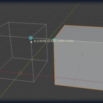
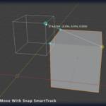
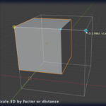
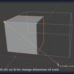
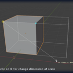
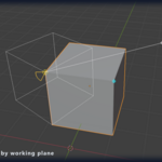
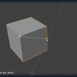
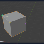
Documentation
Complete user guide — v1.8
TABLE OF CONTENTS
PART 1 — GETTING STARTED
1. Installation
2. Quick Start
3. Interface Overview — Sidebar & Pie Menus
PART 2 — SNAP SYSTEM
4. Snap Types
5. Working Plane
6. Auto Working Plane (Edit Mode)
7. SmartTrack
PART 3 — TRANSFORM TOOLS (Alt+W)
8. Move
9. Scale
10. Rotate
11. Rotate 3D
12. Mirror
13. Array
14. Repeat
15. Measure
16. Gumball (NEW v1.8)
PART 4 — CREATE GEOMETRY (Alt+A)
17. Box (3 modes)
18. Sphere & Ellipsoid (5 modes)
19. Cylinder, Cone, Pyramid, Tube
20. Circle & Ellipse
21. Plane & Polygon
22. Torus (3-point)
23. Draw — Polyline, NURBS, Bezier, Text
PART 5 — CREATE OBJECTS (Alt+E)
24. Lights, Camera, Armature, Lattice
25. Empties & Light Probes
PART 6 — SURFACES (Alt+C)
26. Extrude — 5 modes
27. Loft (updated v1.8)
28. Patch Surface
29. Boundary Surface
PART 7 — MODIFIERS (Alt+X)
30. Offset Curve
31. Sweep 1 / 2 Rails
32. Pipe Along Curve
33. Revolve
34. Tween Curves & Surfaces
35. Shell
36. Inset Face Edge
37. Push/Pull Polysurface
38. Blend Curves
39. Rebuild Curve
40. Knife (NEW v1.8)
41. Split by Plane (NEW v1.8)
PART 8 — REFERENCE
42. Coordinate Input (NEW v1.8)
43. Copy Mode
44. Axis Constraints
45. Numeric Input
46. Live Measurement
47. Edit Mode
48. Supported Object Types
49. Settings Panel & Edit Shortcuts
50. Complete Keyboard Reference
51. F9 Redo Panels
52. Troubleshooting
PART 1
Getting Started
1
Installation
Requirements: Blender 4.2 or later (extension format). Python 3.11–3.13. NumPy optional (only used by Patch B-Spline mode). No other external dependencies.
1 Open Edit → Preferences → Get Extensions → Install from Disk
2 Select the osnap_plus_v1_8.zip file
3 Enable the checkbox next to "OSnap+ — Precision Object Snap" and confirm the version reads 1.8
4 In the 3D Viewport, press N to open the sidebar, or any of Alt+W / Alt+A / Alt+E / Alt+C / Alt+X to open a pie menu
Updating from v1.7 or earlier: Disable the previous version first (Preferences → Get Extensions → OSnap+ → Disable), then install v1.8 from disk and enable it. A full Blender restart is recommended so the previous code is unloaded from memory. Your scene settings and keymaps will be preserved.
2
Quick Start
OSnap+ uses a point-by-point workflow for all transformations. You click snap points — vertices, edge midpoints, face centers, intersections — and the tool computes the operation from those points. No more eyeballing positions.
Your first move:
1. Select an object
2. Press N → click Move in the Quick Tools section (or press Alt+W → Move in the pie)
3. Hover near a vertex — a green square □ appears
4. Click to set the origin point (a yellow crosshair marks it)
5. Move to the destination — a wireframe preview shows the result
6. Click to confirm — the object moves precisely
During the destination phase, you can:
X / Y / Z — constrain to an axis (red/green/blue line shown)
Shift+X/Y/Z — constrain to a plane
= — type exact X / Y / Z coordinates in the Work Plane frame (NEW v1.8 — see section 42)
0–9 . - — type an exact distance, then Enter
C — toggle copy mode (cycle: independent / linked / off)
P — project the snap point onto the working plane
Esc — cancel the operation
3
Interface Overview — Sidebar & Pie Menus
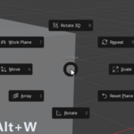
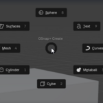
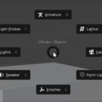
OSnap+ provides two equivalent ways to access every tool: a sidebar in the N-panel for mouse-driven workflows, and 5 pie menus bound to Alt+W/A/E/C/X for keyboard-driven workflows. Use whichever fits your style — or mix both.
Sidebar (press N)
Press N in the 3D Viewport and click the OSnap+ tab. The sidebar is organized into collapsible sections that you expand only when needed:
Tool sections (5)
▶ Quick Tools (Alt+W) — Move, Scale, Rotate, Rotate 3D, Mirror, Measure, Repeat, Array, Work Plane, Gumball
▶ Create Geometry (Alt+A) — Box, Sphere, Cylinder/Cone, Circle, Plane, Torus, Draw
▶ Create Objects (Alt+E) — Lights, Camera, Empties, Armature, Light Probes, Lattice
▶ Surfaces (Alt+C) — Extrude (5 modes), Loft, Patch, Boundary
▶ Modifiers (Alt+X) — organized by category: Curves, Sweep, Tween, Solid, Cut
Info / settings sections
▶ Saved Work Planes — store, restore, update and delete named working planes (NEW v1.8)
▶ Snap Types — toggle each snap type, set snap radius, enable Auto WP, pick the snap engine
▶ Legend — visual markers and supported object types
▶ Active Shortcuts — quick-reference list of modal shortcuts
▶ Performance — mode selector (Light / Heavy / Minimal / Auto) and live object count
Inside each tool section, tools are arranged in a 3-column grid so the whole catalogue fits in a compact panel. The expand/collapse state of every section is saved per scene.
At the bottom of the sidebar, an Edit Shortcuts section lets you search, modify, and reset every keymap inline without leaving the viewport.
Pie menus
Each pie menu opens at the cursor location for fast access. The 5 pies match the 5 tool sections of the sidebar:
| HOTKEY | PIE MENU |
|---|---|
| Alt+W | Quick Tools (Move, Scale, Rotate, etc.) |
| Alt+A | Create Geometry (primitives, draw) |
| Alt+E | Create Objects (lights, camera, empties) |
| Alt+C | Surfaces (extrude, loft, patch, boundary) |
| Alt+X | Modifiers — 5 category sub-pies: Curves ▸ Sweep ▸ Tween ▸ Solid ▸ Cut ▸ |
Modifiers pie organization (updated v1.8): The Alt+X pie now groups tools into 5 category sub-pies that mirror the sidebar's Modifiers section — Curves (Offset, Blend, Rebuild), Sweep (Sweep 1, Sweep 2, Pipe, Revolve), Tween (Curves, Surfaces), Solid (Shell, Inset, Push/Pull), and Cut (Knife, Split by Plane). Click a category to open its sub-pie.
Customizing shortcuts: Every keymap can be changed in the sidebar's Edit Shortcuts section, with search and per-key reset. Changes are persistent across Blender sessions.
PART 2
Snap System
4
Snap Types
OSnap+ provides 9 snap types, each with a distinct colored marker. Toggle each type on/off in the sidebar (N → OSnap+ → Snap Types).
| MARKER | TYPE | COLOR | DESCRIPTION |
|---|---|---|---|
| □ | Vertex | Green | Mesh vertex, bone head/tail, lattice point, curve control point, grease pencil point. |
| ◎ | Edge Midpoint | Orange | Exact center of any mesh edge. |
| + | Edge Point | Blue | Closest point on any edge (not just endpoints or midpoint). v1.8: now perspective-correct — the point sits exactly under the cursor even on edges receding in depth. |
| ◇ | Face Center | Purple | Geometric centroid of any face (tris, quads, n-gons). |
| ⬚ | On Surface (NEW v1.8) | Violet | Any point on a face surface, found by raycast under the cursor. Objects always win over the Working Plane, so you can land precisely anywhere on a model. |
| △ | Object Center | Pink | Origin (pivot) of any visible object. |
| ⊥ | Perpendicular | Cyan | Foot of perpendicular from the origin point onto any edge. Only active after an origin is set. |
| ✕ | Intersection | Yellow | Where two edges physically cross in 3D space, or where an edge pierces a face. |
| ◈ | SmartTrack | Cyan | Projected alignment lines from tracked reference points (see section 7). |
Priority order: Vertex → Edge Midpoint → Intersection → Perpendicular → Edge Point → Face Center → On Surface → Object Center. When multiple snap candidates exist within the snap radius, the highest-priority one wins.
Snap radius: Detection radius in pixels (5–60, default 20). Adjustable in the Snap Types section. Larger = easier to snap on dense scenes, smaller = more precise.
Snap engine (NEW v1.8)
A new Raycast engine (default) casts a ray under the cursor and analyzes only the face it hits, using the C-level BVH for O(log n) lookups. This removes the old per-object vertex-scan ceiling, so dense CAD meshes that previously dropped out of snapping now resolve smoothly. A Legacy engine remains selectable in the Snap Types section if you prefer the classic behavior.
5
Working Plane
Access: Alt+W → Work Plane | Sidebar → Quick Tools → Work Plane
Defines a custom construction plane. When active, all axis constraints (X/Y/Z) follow this plane instead of world axes. A blue grid is displayed in the viewport to confirm the plane is active.
| CLICKS | RESULT |
|---|---|
| 1 click + Enter | Moves the origin, keeps the current normal direction |
| 2 clicks + Enter | Origin + X axis direction (normal computed perpendicular) |
| 3 clicks | Origin + X axis + Y axis = fully custom plane orientation |
Press Alt+W → Reset Plane (or sidebar → Reset WP) to return to world XY.
Effect on tools: When the working plane is active, pressing X constrains along the plane's X axis (not world X). Same for Y and Z. Free snap (no geometry under cursor) projects onto the working plane instead of world XY.
Always-Visible plane (NEW v1.8)
The working plane grid now stays drawn continuously in the viewport (toggle "Always Show WP" in Quick Tools), not just while a tool is running — so your construction frame is always visible as a reference. The overlay redraws live as you set or reset the plane.
Saved Work Planes (NEW v1.8)
A dedicated Saved Work Planes section lets you keep a library of named planes inside the .blend file:
• Save — set a plane, then press + to store it with a name
• Restore — click a saved plane to make it the active Working Plane again
• Update / Delete — overwrite a saved plane with the current one, or remove it
Saved planes persist with the scene, so frequently-used construction planes (a sloped roof, a façade, a section cut) are one click away in any session.
See also: the Gumball (section 16) aligns Blender's native gizmo to the active Working Plane.
6
Auto Working Plane (Edit Mode)
Toggle: Sidebar → Snap Types → "Auto WP (Edit Mode)"
When enabled, launching any tool in Edit Mode automatically creates a temporary working plane aligned with your current selection.
| SELECTION | AUTO WORKING PLANE |
|---|---|
| Face(s) selected | Center = face center, Normal = face normal |
| Edge(s) selected | Center = edge midpoint, X = edge direction, Normal from adjacent faces |
| Vertex/vertices | Center = vertex position, Normal = averaged vertex normal |
By default the auto plane is temporary — when the tool finishes, the previous working plane is restored. An "AUTO WP" indicator appears in the viewport while active.
Persistent Auto-WP (NEW v1.8): A new option keeps the auto-generated plane active after the tool finishes (instead of reverting), so a series of edits on the same face all share the same frame. Toggle it alongside the Auto WP option.
7
SmartTrack
Toggle: Sidebar → Snap Types → "SmartTrack"
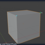
SmartTrack projects alignment axes from reference points you "hover-track", letting you create precise alignments without construction geometry or guides.
How to activate a reference point:
1. During any tool, hover the cursor on a snap point (vertex, edge mid, face center, etc.)
2. Stay still for 0.8 seconds — a cyan progress arc fills around the marker
3. When the arc completes, the point is tracked — cyan axes project from it
4. Repeat to track up to 5 points simultaneously
Projected alignment axes:
World X / Y / Z — from each tracked point
Origin → ST — vector from current operation origin to tracked point
ST → ST — vectors between all pairs of tracked points
When your cursor crosses a projected line, the SmartTrack snap (◈ cyan) activates on the intersection. Press Backspace to remove the most recent tracked point. The status bar shows [ST:N] with the active count.
Use case: To align an object with the corner of one face and the edge of another, hover-track both points, then snap onto the intersection of the projected lines.
PART 3
Transform Tools (Alt+W)
8
Move
Access: Alt+W → Move | Sidebar → Quick Tools → Move
Workflow: 2 clicks — Origin → Destination
Step 1 — Origin: Click a snap point on any object. This sets the reference point for the move. A yellow crosshair + marks the origin.
Step 2 — Destination: Move the cursor to the target location. A wireframe preview shows where the object will go. Click to confirm.
During step 2 you can:
X/Y/Z — constrain to an axis
Shift+X/Y/Z — constrain to a plane
= — type exact X/Y/Z coordinates (see section 42)
0–9 . - — type exact distance
C — toggle copy mode
P — project snap on working plane
Esc — cancel
Note: If no geometry is under the cursor but an axis constraint is active, the snap falls back to the constrained axis or plane through the origin. If no constraint is set, it falls back to the working plane (or world XY).
9
Scale
Access: Alt+W → Scale | Sidebar → Quick Tools → Scale
Two workflows available:
Scenario 1 — Direct factor (2 clicks)
Click 1: Pivot point (center of scale)
Type: Factor value (e.g. 2 = double size, 0.5 = half size)
Press: Enter or Click to confirm
Scenario 2 — By distance (3 clicks)
Click 1: Pivot point
Click 2: Reference point — defines the source distance (pivot → ref)
Click 3 or type: Target point or target distance — the factor is computed as target_distance / reference_distance
Example: If reference is 3m and target is 6m, the factor is 6/3 = 2×
Scale modes (press Q to cycle):
| MODE | BEHAVIOR |
|---|---|
| Uniform 3D | Scales equally in all 3 directions |
| Plane 2D | Scales in the working plane, keeps the normal axis unchanged |
| Axis 1D | Scales only along the direction from pivot to reference point |
Key detail: The scale direction is defined by the vector from pivot to reference point, NOT by world axes. This allows scaling along any arbitrary direction.
10
Rotate
Access: Alt+W → Rotate | Sidebar → Quick Tools → Rotate
Workflow: 3 clicks — Center → Start angle → End angle
Click 1: Center of rotation (pivot)
Click 2: Start direction (defines 0 degrees)
Click 3: End direction, or type degrees + Enter
Rotation axis: Press X, Y, or Z to change (default: Z, or working plane normal if WP active).
An arc indicator shows the rotation angle in real-time, along with the degree value near the cursor.
11
Rotate 3D
Access: Alt+W → Rotate 3D | Sidebar → Quick Tools → Rot 3D
Workflow: 4 clicks — Center → Axis point → Start → End
Click 1: Center of rotation
Click 2: Axis direction point — the rotation axis is the vector from center to this point
Click 3: Start direction
Click 4: End direction, or type degrees + Enter
Use case: Rotate around any arbitrary axis in 3D space. Unlike the standard Rotate tool which is limited to X/Y/Z, this lets you define any direction by clicking two points.
12
Mirror
Access: Alt+W → Mirror | Sidebar → Quick Tools → Mirror
Mirror selected objects across an axis (2 points) or a plane (3 points). Switch methods on the fly with A / P.
A — Axis method (2 points, default)
Click 1: First axis point
Click 2: Second axis point — mirrors across the line between the two clicks
P — Plane method (3 points)
Click 1: Plane origin
Click 2: X direction
Click 3: Y direction — mirrors across the plane defined by the 3 clicks. The plane follows the Working Plane frame, not the camera.
Copy modes (press C to cycle):
C ×1 — independent copy (blue wireframe preview)
C ×2 — linked copy, shared mesh data (green wireframe preview)
C ×3 — no copy: mirror moves the original (white wireframe preview)
Use case: Symmetric architecture — pick a wall edge as axis, mirror your facade detailing. For arbitrary mirror planes (e.g. across a slanted floor), use the 3-point plane method.
13
Array
Access: Alt+W → Array | Sidebar → Quick Tools → Array
After launching, press G, R, or S to choose the array mode.
G — Linear Array
Click 1: Origin point
Click 2: Direction + spacing (vector from origin to this point = offset between copies)
Type + Enter: Number of copies
Example: Origin on corner A, direction to corner B (2m away), count 5 = 5 copies spaced 2m apart
R — Polar Array
Click 1: Center of rotation
Type + Enter: Number of items (distributed over 360°)
Axis: Uses the working plane normal (or world Z if no working plane)
S — Planar Array
Click 1: Origin
Click 2: X direction + spacing
Click 3: Y direction + spacing
Type + Enter: Grid count as NxM (e.g. 3x4) or a single number for a square grid
All array modes show a real-time wireframe preview of every copy before you confirm.
14
Repeat
Access: Alt+W → Repeat | Sidebar → Quick Tools → Repeat
Repeats the last OSnap+ action (Move, Scale, or Rotate) N times on the currently selected objects.
Type: Number of repetitions (default: 1)
Press: Enter to confirm
Example: Move an object 5m, then Repeat ×3 = the object moves 15m more (3 × 5m).
15
Measure
Access: Alt+W → Measure | Sidebar → Quick Tools → Measure
Workflow: 2 clicks — Start point → End point
Click 1: Start snap point
Click 2: End snap point — reports total distance + XYZ breakdown
The result is displayed in the header bar and printed to Blender's info area for copying. No object is modified — Measure is purely informational.
16
Gumball (NEW v1.8)
Toggle: Sidebar → Quick Tools → Gumball
The Gumball brings up Blender's combined Move / Rotate / Scale gizmo, but pivoted at the center of the selected geometry and aligned to the active Working Plane. Define a plane on an inclined surface and every gizmo manipulation then happens in that frame — drag along the plane's X/Y/Z, rotate about its normal, scale within it.
How it works:
• A custom "OSnap WP" transform orientation is created and kept in sync with the Working Plane
• The gizmo pivot is placed at the median of the current selection
• Toggling the Gumball off restores your previous transform orientation and pivot settings
Use case: Working on a slanted roof plane — set a Work Plane on the slope, enable the Gumball, and nudge/rotate elements directly in the roof's frame without fighting world axes.
PART 4
Create Geometry (Alt+A)
All geometry tools have a live wireframe preview during construction. After creation, every operator exposes a F9 redo panel with full parameter access (resolution, subdivisions, fill type, etc.).
17
Box (3 modes)
Cube (classic)
Click 1: Center point
Creates a unit cube centered on the snap. Use F9 to adjust size.
Box 3pts (precise)
Click 1: First corner
Click 2: X-axis corner — defines width and X orientation
Click 3: Y-axis corner — defines depth and Y orientation
Click 4 or type: Height
Creates a box with arbitrary orientation, perfectly aligned with 3 snap points (typical use: matching an existing slab or wall corner).
Box 2pts (diagonal)
Click 1: First corner
Click 2: Opposite corner — defines width and depth on the working plane
Click 3 or type: Height
Aligned with the working plane axes. Fastest way to box a rectangular footprint.
18
Sphere & Ellipsoid (5 modes)
Sphere (classic) / Ico Sphere
Click 1: Center point. Creates a unit sphere; size adjustable in F9.
Sphere Centre+R
Click 1: Center
Click 2 or type: Radius point or numeric radius. Live preview shows the wireframe sphere expanding.
Sphere 3pts
Click 1, 2, 3: Three points on the sphere's surface. The sphere is fit through these three points (center + radius computed automatically).
Ellipsoid
Click 1: Center
Click 2: X radius
Click 3: Y radius
Click 4 or type: Z radius
F9 options: Mesh type (UV / Ico / Quad), subdivision count, smooth shading.
19
Cylinder, Cone, Pyramid, Tube
Cylinder (classic) / Cone (classic)
Click 1: Center. Creates a unit cylinder/cone; configure in F9.
Cylinder 3pts / Cone 3pts
Click 1: Base center
Click 2: Radius (defines base circle on the working plane)
Click 3 or type: Height (along the working plane normal)
Pyramid
Click 1: Base center
Click 2: Base half-size
Click 3 or type: Apex height (N-sided base configurable in F9, default 4)
Tube
Click 1: Center
Click 2: Outer radius
Click 3: Inner radius
Click 4 or type: Height. Hollow cylinder, ideal for pipes and rings.
F9 options: Side count, fill type (Ngon / Triangle Fan / Nothing), smooth shading.
20
Circle & Ellipse
Circle (classic)
Single click at center. Unit-sized circle, adjustable in F9.
Circle Centre+R (2pt — true flat circle)
Click 1: Center
Click 2 or type: Radius point. Creates a true 2D circle in the working plane (not a sphere wireframe slice).
Bezier Circle
Creates a Blender Bezier curve circle (parametric, editable in Edit Mode). Useful as a profile for Sweep or Pipe.
F9 options: Vertex count, fill type (Ngon / Triangle Fan / Nothing).
21
Plane & Polygon
Plane (classic)
Single click at center. Unit plane on the working plane.
Plane 2pt (diagonal)
Click 1: First corner
Click 2: Opposite corner. Rectangle aligned with the working plane axes.
Plane 3pt (oriented)
Click 1: First corner
Click 2: X-axis corner
Click 3: Y-axis corner. Free-orientation rectangle aligned with 3 snap points.
Polygon N pts
Click each vertex in order. Press Enter to close the polygon.
Creates a flat n-gon mesh. Snap each vertex on existing geometry for perfect fits.
22
Torus (3-point)
Torus 3pt
Click 1: Center
Click 2: Major radius (size of the ring, on the working plane)
Click 3: Minor radius (tube thickness)
A full wireframe preview shows the torus during construction — 8 section rings plus the profile circle — so you can see exactly what the result will look like.
F9 options: Major segments, minor segments, smooth shading.
23
Draw — Polyline, NURBS, Bezier, Text
Polyline
Click each point in order. Press Enter to finish (open) or C to close. Each point uses full snap targeting.
Creates a Blender curve made of straight line segments. Perfect for tracing the outline of a building footprint or floor plan.
NURBS Curve
Same workflow as Polyline, but creates a smooth NURBS curve interpolating the clicked control points. Press C to close into a cyclic curve.
Bezier / Bezier Circle
Single-click placement of a default Bezier curve at the snap point. Edit in Edit Mode afterwards.
Text
Places a text object at the snap point. Edit content and font in the object's properties.
Polyline / NURBS keyboard: Enter = finish open, C = close cyclic, Backspace = remove last point, Esc = cancel entirely.
PART 5
Create Objects (Alt+E)
All non-geometry objects (lights, camera, empties, etc.) are placed via a single click with full snap targeting. The object's origin is positioned exactly at the snap point.
24
Lights, Camera, Armature, Lattice
Lights — Point / Sun / Spot / Area
Click: Place the light at the snap point
Esc: Cancel and delete the created light
Camera
Click to place. The camera looks toward the viewport's current view direction. Adjust orientation afterward in the camera's properties.
Armature / Lattice
Single-click placement at the snap point. Useful when you want to anchor a rig or lattice to an existing mesh vertex.
25
Empties & Light Probes
Empties: Plain Axes, Arrows, Single Arrow, Circle, Cube, Sphere. Single-click placement.
Light Probes: Reflection Cubemap, Irradiance Volume, Reflection Plane. Single-click placement for Eevee rendering setup.
Tip: Empties are ideal as parents/controllers, snap them onto mesh vertices for clean rigging anchor points.
PART 6
Surfaces (Alt+C)
26
Extrude — 5 modes
Five distinct extrude operators, each tailored to a specific workflow. All work in both Object Mode (extrude entire faces of the active object) and Edit Mode (extrude selected faces/edges/vertices).
Linear
Click 1: Origin point on the source face/edge
Click 2 or type: Destination — defines length and direction
Standard linear extrusion along the chosen direction. Axis constraints (X/Y/Z) work as expected.
Tapered
Click 1: Origin
Click 2: Direction and length
F9: Taper factor (0 = no taper, 1 = collapse to point). Useful for pyramidal roofs, draft angles on castings.
To Point
Click 1: Apex point — all source faces extrude toward this single point
Creates conical/pyramidal shapes where the source face converges to a single apex. Snap onto any vertex for precise apex placement.
Along Curve
Setup: Select the source mesh AND a curve object
Run: The source face sweeps along the curve path, with rotation-minimizing frames for clean orientation.
Extrude Curve
Setup: Select one or more curves
Click 1: Origin point
Click 2 or type: Direction + distance
All selected curves are extruded simultaneously, with live preview shown on every curve.
Closed curves → sealed volumes: When a selected curve is closed (cyclic), the result is a watertight volume with bottom cap + top cap + recalculated outward normals.
Open curves → surfaces: Open curves produce an open quad ribbon (the side wall only).
F9 options for all modes: Resolution, taper factor (Tapered only), individual extrusion (per-face vs unified), normal correction.
27
Loft (updated v1.8)
Access: Alt+C → Loft | Sidebar → Surfaces → Loft
Setup: Select 2 or more curves (any topology — Bezier, NURBS, polylines)
Loft creates a smooth surface across selected curves. The source order is auto-computed by proximity, so you don't need to select curves in the right sequence.
Loft v2 changes (v1.8):
• No more twist on closed sections — section directions AND seams are now aligned jointly (the solver optimizes both together), so stacked circles and closed profiles no longer spiral
• Smooth interpolation — a Catmull-Rom pass runs through the sections for a fairer surface
• Closed Loft — loop the surface back from the last section to the first
• Cap Ends — seal the first and last sections for a watertight volume
How it works
1. Select 2+ curves and run Loft (Alt+C → Loft)
2. The 2 most distant curves become the chain endpoints; remaining curves are ordered by nearest-neighbor between them
3. The surface is generated and the result is shown immediately
4. Open the F9 redo panel to adjust resolution, mode, output type, sync/seam/closed/cap options, OR reorder the chain
F9 options
| PARAMETER | EFFECT |
|---|---|
| Resolution | Number of points sampled along each curve (4–256, default 24) |
| Cross Sections | Number of interpolated sections inserted between source curves (smoother surface, Catmull-Rom) |
| Mode | Normal (smooth through all) / Loose (smooth ends, relaxed middle) / Straight Sections (sharp angles) |
| Sync Directions / Align Seams | v1.8 — keep all sections wound the same way and aligned, preventing twist |
| Closed Loop / Cap Ends | v1.8 — loop back to the first section / seal the ends into a closed volume |
| Output | Mesh (quads) or NURBS surface |
| Order | Pipe-separated curve names defining the chain order. Clear the field to re-apply proximity sort. |
Reorder by Click
If the auto-sort doesn't produce the order you want, click "Reorder by Click" in the F9 panel:
1. An interactive overlay appears: each source curve gets a small · marker on its center
2. Hover near a curve — a yellow ? shows it's available for picking
3. Click each curve in the order you want — a green numbered badge appears (1, 2, 3…) with connecting lines
4. Press Enter when done (or click every curve). Any unpicked curves are appended in auto-sorted order.
5. The Loft regenerates instantly with your new order.
Use case: 5 cross-sections of a boat hull — proximity sort handles standard cases automatically. For unusual configurations (curves in a star pattern, for instance), click to reorder.
28
Patch Surface
Access: Alt+C → Patch | Sidebar → Surfaces → Patch
Setup: Select any combination of curves, mesh objects (point sets), or empties to act as patch inputs
Patch fits a smooth surface through a collection of curves and/or points. Three algorithms are available, selectable in the F9 panel:
| ALGORITHM | DESCRIPTION |
|---|---|
| B-Spline (LSQ) | Least-squares fit of a B-Spline surface through all input points. Smooth, fairs out noise. Requires NumPy. |
| CDT (triangulation) | Constrained Delaunay triangulation — preserves exact input points, no smoothing. |
| NURBS Surface | True parametric NURBS surface output (editable in Edit Mode afterwards). |
AutoTrim: If trimming curves are selected (closed curves lying on the patch surface), Patch can boolean-cut the resulting surface to match them. Enable in F9.
F9 options: Algorithm, U/V resolution, control point counts, smoothing factor, AutoTrim toggle.
29
Boundary Surface
Access: Alt+C → Boundary | Sidebar → Surfaces → Boundary
Fills closed curves to create surfaces. Works with a single closed curve (fan/grid fill) or a grid of curves (Coons patch).
Single closed curve
Select a closed curve and run. Generates a flat or curved fill mesh respecting the curve's 3D position.
Grid of curves (Coons)
Select 4 curves forming a closed quadrilateral boundary. The Coons patch algorithm bilinearly interpolates a smooth surface that respects all 4 boundary curves.
F9 options: U/V resolution, fill type (Quads / Triangles), adaptive resolution.
PART 7
Modifiers (Alt+X)
The Modifiers pie (Alt+X) is organized into 5 category sub-pies that mirror the sidebar: Curves (Offset, Blend, Rebuild), Sweep (Sweep 1, Sweep 2, Pipe, Revolve), Tween (Curves, Surfaces), Solid (Shell, Inset, Push/Pull), and Cut (Knife, Split by Plane). Click a category to open its sub-pie.
30
Offset Curve
Access: Alt+X → Curves ▸ Offset | Sidebar → Modifiers → Offset
Setup: Select one or more curves
Workflow: Run the operator, drag to define the offset distance and side, click to confirm.
F9 options:
Distance — numeric offset distance
Side — Left / Right / Both Sides
Corner Type — Sharp (miter) or Rounded (arc fillet)
Output — Polyline or NURBS curve
Use case: Wall thickness from a floor plan polyline — Both Sides + Sharp corners with distance = half the wall thickness.
31
Sweep 1 / 2 Rails
Access: Alt+X → Sweep ▸ | Sidebar → Modifiers → Sweep 1 / Sweep 2
Sweep 1 Rail
Setup: Select a profile curve + a rail curve (any order)
Active object = rail, other selected = profile
The profile is swept along the rail with rotation-minimizing frames. Sharp corners on the rail produce miter joints automatically.
Sweep 2 Rails
Setup: Select 1 profile + 2 rail curves
The profile sweeps between the two rails, scaling and rotating to match both. Useful for ramp railings, varying-section beams, parametric architecture.
F9 options: Resolution along rail, profile sampling, twist factor, scale variation, cap ends.
32
Pipe Along Curve
Access: Alt+X → Sweep ▸ Pipe | Sidebar → Modifiers → Pipe
Setup: Select one or more curves
Run: Each selected curve is converted to a tube of constant radius.
F9 options:
Radius — tube radius
Resolution V — number of sides around the tube (default 12)
Resolution U — segments along the curve length
Cap Ends — fill the tube ends
Smooth shading
Use case: Plumbing, electrical conduits, structural reinforcement bars, hand-rails.
33
Revolve
Access: Alt+X → Sweep ▸ Revolve | Sidebar → Modifiers → Revolve
Setup: Select a profile curve
Click 1: Axis point 1
Click 2: Axis point 2 — defines the rotation axis
Hotkeys for quick axes: X / Y / Z = use world axis instead of clicking 2 points
By default, revolves a full 360°. Adjust to a partial angle in F9 for arcs and segments.
F9 options: Angle (0–360°), segments, cap ends. Profile direction relative to axis determines whether the result is a vase, bowl, ring, etc.
34
Tween Curves & Surfaces
Access: Alt+X → Tween ▸ | Sidebar → Modifiers → Tween
Generates intermediate curves or meshes interpolated across a chain of source objects. Use cases: morphing, animation reference, parametric variations, fillets between profile sections.
Key behaviors:
• Count is global — the value is the TOTAL number of intermediates across the whole chain (not per-pair)
• Tween Surfaces supports 2+ meshes
• Proximity auto-sort orders the chain automatically
• "Reorder by Click" in F9 for interactive ordering
Tween Curves
Setup: Select 2+ curves
Run: Curves are auto-sorted by proximity and N intermediate curves are generated
F9 options:
Count — total number of intermediate curves along the chain (1–100)
Output — Polyline / NURBS
Easing — Linear / Smooth (Hermite S-curve)
Auto Flip / Flip B — automatic or manual reversal of every other curve to prevent twisting
Order — chain order (pipe-separated names; clear for re-sort)
Reorder by Click — interactive ordering (see below)
Tween Surfaces
Setup: Select 2+ mesh objects that share the same vertex count
Run: Meshes are sorted by proximity, N intermediate meshes are interpolated vertex-by-vertex
Requirement: All source meshes must have identical vertex counts. The interpolation is vertex-to-vertex (vert N of source A → vert N of source B). To create suitable input, use the same primitive (e.g. 3 deformed copies of the same UV sphere) or Loft a series of curves into similar quad meshes.
F9 options:
In-Between Count — total number of intermediate meshes (1–200)
Easing — Linear / Smooth
Order — same as Tween Curves
Reorder by Click (interactive)
In F9, click "Reorder by Click" to enter interactive ordering mode. Same workflow as Loft (see section 27):
• Each source object gets a small dot at its center in the viewport
• Click each source in the order you want — numbered green badges + connecting lines appear
• Enter to confirm partial order (unpicked sources auto-appended), or click all of them
• Tween regenerates instantly with the new order
Pro tip: Global Count distribution — if you have 3 sources (A, B, C) and Count=10, you get 10 evenly-spaced intermediates along the entire A→B→C chain (5 between A-B and 5 between B-C, approximately).
35
Shell
Access: Alt+X → Solid ▸ Shell | Sidebar → Modifiers → Shell
Setup: Select one or more mesh objects (or faces in Edit Mode)
Shell creates a solid thickness on selected mesh objects/faces. Unlike Blender's Solidify modifier, OSnap+ Shell:
• Works on multiple meshes simultaneously
• Supports openings (skip selected faces to create holes)
• Provides three thickness directions: IN, OUT, BOTH
• Returns boolean-clean topology suitable for further CAD operations
F9 options:
| OPTION | EFFECT |
|---|---|
| Thickness | Distance to offset (positive number) |
| Direction | OUT (outward only) / IN (inward only) / BOTH (centered on the surface) |
| Openings | If Edit Mode + face selection, unselected faces become openings (e.g. windows in a wall) |
| Even Thickness | Preserves uniform thickness at corners (recommended for boolean operations) |
Use case: Turn a NURBS-style architectural surface into a wall with thickness, with door/window openings cut into specific faces.
36
Inset Face Edge
Access: Alt+X → Solid ▸ Inset | Sidebar → Modifiers → Inset
Setup: Select a NURBS surface, polysurface, or mesh panel
Creates a uniform offset edge inside each face of the selected surface. Unlike Blender's native Inset Faces (which uses a uniform scale toward the face center, distorting on non-uniform faces), this operator produces a geometrically uniform gap on every side of every face — the result is the same offset distance everywhere, regardless of face shape.
F9 options:
Distance — inset depth from each edge
Mode — Planar (faster, for flat faces) / On-Surface (slower, for curved NURBS panels — uses RhinoCommon-style edge offset along the surface)
Per-Face / Joined — whether to inset each face independently or globally
Use case: Facade paneling — create a uniform 2cm gap around every metal panel of a curtain wall. The result is real geometric uniformity, not a scaled approximation.
37
Push/Pull Polysurface
Access: Alt+X → Solid ▸ Push/Pull | Sidebar → Modifiers → Push/Pull
Setup: In Edit Mode, select one or more faces. Alternatively, hover the cursor over a face in Object Mode.
Push/Pull provides true CAD-style extrusion with two distinct modes:
PUSH mode (default)
Creates a new solid volume on top of the selected face(s), or carves a cavity if you push in the negative direction.
Internally uses boolean Union (for positive push) or Difference (for negative push, i.e. cavity).
MODIFY mode (hold Alt)
Free deformation — the selected face is simply translated along its normal, like Blender's native extrusion. No boolean operation. Use this when you want to push a face inward without creating a new volume.
Workflow
1. In Edit Mode, select the face(s) you want to push (or hover the cursor over a face in Object Mode)
2. Launch Push/Pull (Alt+X → Solid ▸ Push/Pull)
3. Move the mouse to control distance, or type a numeric value
4. Press Alt any time to toggle between PUSH and MODIFY modes
5. Use X / Y / Z for axis constraints if needed
6. Click or Enter to confirm; Esc to cancel
Live preview
PUSH mode: A blue wireframe outline shows where the new volume will be created (positive direction) or carved (negative).
MODIFY mode: The face is translated live in the viewport, showing the final shape directly.
Per-island grouping
When you select multiple faces, Push/Pull groups them into islands — sets of faces that share at least one edge. Each island is processed as a single boolean operation:
• Adjacent faces → 1 continuous volume (no seam edge between them in the result)
• Non-adjacent faces → separate volumes (independent extrusions, like multiple individual pushes done at once)
Smart cleanup
Boolean operations naturally produce "contre-edges" — parasitic subdivision edges between coplanar faces. Push/Pull's cleanup algorithm:
• Snapshots every vertex position before the boolean
• After the boolean, identifies edges where BOTH endpoints are newly created
• Dissolves only those edges if they're coplanar (within 5°) with surrounding faces
• Welds coincident vertices at junctions
Result: edges from previous Push/Pull operations are always preserved on subsequent pushes, no matter how many times you chain operations. Only the genuine parasitic edges of the current boolean get cleaned.
Even-thickness direction
When multiple adjacent faces are pushed together, the direction vector at shared corners is computed to keep orthogonal thickness rather than averaging the face normals. This prevents the "shrinking corner" artifact that naive extrusion produces.
Use case: Architectural massing — start with a flat slab, push faces upward to create floors, push other faces inward to carve atria and courtyards. All without leaving the source object or breaking topology.
38
Blend Curves
Access: Alt+X → Curves ▸ Blend | Sidebar → Modifiers → Blend
Setup: Select exactly 2 curves
Creates a smooth bridge curve between the endpoints of two existing curves, with G1 (tangent) or G2 (curvature) continuity.
F9 options:
Continuity — Position (G0), Tangent (G1), Curvature (G2)
Resolution — number of points in the blend curve
Bulge — controls the curvature of the bridge (0 = straight line, 1 = maximum curvature)
39
Rebuild Curve
Access: Alt+X → Curves ▸ Rebuild | Sidebar → Modifiers → Rebuild
Setup: Select one or more curves
Reconstructs the selected curve(s) with a clean, uniform control point distribution. Useful to fix imported curves with messy parameterization, or to convert dense polylines into smooth NURBS.
F9 options:
Point Count — number of new control points
Degree — output curve degree (1 = polyline, 3 = cubic NURBS, 5 = quintic NURBS)
Preserve Tangents — keep start/end tangent directions
40
Knife (NEW v1.8)
Access: Alt+X → Cut ▸ Knife | Sidebar → Modifiers → Knife
Setup: One mesh object (Object or Edit Mode)
Knife cuts a mesh surface along a path you draw with snapped points — 2 points for a straight cut, more for a multi-segment polyline. The seam follows your line exactly, segment by segment, only on the faces you draw over, and the mesh stays fully joined (no separation, no new objects).
Workflow
1. Launch Knife (Alt+X → Cut ▸ Knife). From Object Mode it enters Edit Mode automatically.
2. Click snap points across the surface to trace the cut path — every snap type is available, so you can start and end exactly on vertices, edges, or intersections.
3. Press Enter to apply the cut, Backspace to remove the last point, Esc to cancel.
4. When launched from Object Mode, Knife returns to Object Mode once the cut is confirmed.
How the cut is resolved
• Per-segment, surface-only: each segment is cut on a single face, resolved from the segment's midpoint — unambiguous even when an endpoint sits on an edge shared by two faces. The cut never spills onto adjacent faces.
• Collinear with your line: the cut is computed along the drawn line and projected onto the face plane, so it lies exactly under the snap line — no perpendicular drift.
• Multi-face paths: a path crossing several faces divides each one in turn; the face topology is re-evaluated between segments so every cut lands cleanly.
• Joined result: the surrounding geometry stays merged — you get new edges and faces, not a detached piece.
Use case: Splitting a wall face to add a recess line, slicing a panel to follow a snapped reference edge, or scoring a roof surface for a parametric seam — all with exact, snap-driven placement.
41
Split by Plane (NEW v1.8)
Access: Alt+X → Cut ▸ Split by Plane | Sidebar → Modifiers → Split Plane
Setup: One mesh object (Object or Edit Mode)
Split by Plane cuts the entire geometry by a plane you define with three snapped points. A live preview shows exactly where the plane falls while you pick.
| CLICK | DEFINES |
|---|---|
| Click 1 ● | Plane origin |
| Click 2 ● | X direction |
| Click 3 ● | Y direction (the cut normal is X × Y) |
Two behaviors by mode
Edit Mode — Incise
The plane cuts every surface it crosses, leaving the geometry joined. Think of it as a projected-plane knife across the whole mesh — ideal for scoring section lines without separating anything.
Object Mode — Split & Cap
The whole object is split along the plane, the two halves are separated into distinct objects, and each open section is capped into a closed volume. Perfect for cutting a massing model cleanly in two.
F9 options:
Cap — fill each section into a closed face (Object Mode; on by default)
Note: Capping is most reliable on convex sections. Concave shapes that produce several separate section loops on the cut plane may cap imperfectly — incise in Edit Mode and close the openings manually for those cases.
PART 8
Reference
42
Coordinate Input (NEW v1.8)
During any tool that asks for a point, press = to switch from cursor picking to exact coordinate entry — CAD-style numeric placement, right in the viewport.
How it works
1. Start any tool that requests a point (Move, a primitive, Work Plane, Knife, Split by Plane…)
2. Press = — a coordinate field opens with X / Y / Z slots
3. Type a value, press Tab to move to the next axis
4. Press Enter (or click) to place the point at the typed coordinate
Frame of reference: Values are expressed in the active Work Plane frame when one is set — so X / Y / Z follow the plane's axes — or in world coordinates when no Work Plane is active. This makes it easy to type positions relative to an inclined construction plane.
Use case: Placing a point exactly 1.20 m along a wall's Work Plane and 0.90 m up, without any reference geometry to snap to — just press =, type the values, Enter.
43
Copy Mode
During any tool (Move, Scale, Rotate, Mirror), press C to toggle copy mode. The transformation creates a duplicate instead of moving the original.
| KEY | MODE | PREVIEW COLOR |
|---|---|---|
| C ×1 | Independent copy | Blue wireframe |
| C ×2 | Linked copy (shared mesh data) | Green wireframe |
| C ×3 | Normal mode (no copy) | White wireframe |
Note: Copy mode is disabled in Edit Mode (vertices cannot be duplicated this way; use Blender's native Shift+D for that).
44
Axis Constraints
Works exactly like Blender's native axis constraints, but follows the working plane when one is active. Press the same key again to deactivate.
| KEY | CONSTRAINT | LINE COLOR |
|---|---|---|
| X | Constrain to X axis | Red |
| Y | Constrain to Y axis | Green |
| Z | Constrain to Z axis | Blue |
| Shift+X | Constrain to YZ plane | Faded red |
| Shift+Y | Constrain to XZ plane | Faded green |
| Shift+Z | Constrain to XY plane | Faded blue |
Working plane interaction: When a working plane is active, X/Y/Z refer to the plane's axes, not world axes. To temporarily get world constraints, press Alt+W → Reset Plane first.
45
Numeric Input
During any tool's action phase, type numbers on the keyboard for exact values. The typed value appears at the bottom center of the viewport. (For full X/Y/Z coordinate entry, see Coordinate Input, section 42.)
| TOOL | VALUE MEANING |
|---|---|
| Move / Extrude | Distance in Blender units along the current direction or constrained axis |
| Scale (no ref point) | Direct factor (2 = double size, 0.5 = half size) |
| Scale (with ref point) | Target distance — factor is computed as value / reference_distance |
| Rotate / Rotate 3D / Revolve | Angle in degrees |
| Array | Count (for planar: NxM format like 3x4) |
| Repeat | Number of repetitions |
| Primitives (cube, sphere, etc.) | Dimension (radius, height, side) depending on construction phase |
Accepted keys: 0–9, . (decimal), - (negative). Backspace deletes the last character. Enter or Click confirms.
46
Live Measurement
A real-time measurement value is displayed near the cursor during all actions, so you always know what's happening before clicking.
Move: D: 2.3456 (1.200, 1.800, 0.500) — total distance + XYZ breakdown
Scale (ref phase): Ref: 3.0000 — reference distance from pivot
Scale (target phase): D: 6.0000 ×2.0000 — target distance + computed factor
Rotate: ∠ 45.00° — current angle from start direction
Array (linear): Spacing: 2.5000 — distance between copies
Extrude: H: 1.2000 — extrusion height
When typing a numeric value, the measurement display switches to show the typed value instead of the cursor position.
47
Edit Mode
All OSnap+ tools work in Edit Mode. Instead of transforming entire objects, they transform the selected vertices, edges, or faces.
| TOOL | OBJECT MODE | EDIT MODE |
|---|---|---|
| Move | obj.location += delta | Selected verts += delta |
| Scale | World matrix scale | Selected verts scaled around pivot |
| Rotate | obj.rotation_euler | Selected verts rotated around pivot |
| Mirror | Mirrors objects across axis/plane | Mirrors selected verts across axis/plane |
| Copy mode | Duplicates objects | Disabled |
| Preview | Full wireframe | Selected edges transform live; unselected dimmed |
Snap detection in Edit Mode sees the mesh being edited in real-time via bmesh.from_edit_mesh() — so you can snap onto verts you've just created in the same session.
Cut tools: Knife and Split by Plane are Edit-Mode operations. Launched from Object Mode they switch into Edit Mode automatically and (for Knife / incise) return to Object Mode when finished.
48
Supported Object Types
| TYPE | SNAP AVAILABLE |
|---|---|
| Mesh | Vertex, edge mid, edge point, face center, on-surface, origin, perpendicular, intersection |
| Curve / Surface / Text | Control points, Bezier handles, tessellated geometry |
| Metaball / Volume | Converted geometry + origin |
| Armature | Bone head and tail positions |
| Lattice | All lattice control points |
| Camera | Origin + DOF focus target (if set) |
| Light / Light Probe / Speaker / Empty | Origin point only |
| Grease Pencil | All stroke points |
| Collection Instances | Full geometry of all objects inside the collection, recursively |
49
Settings Panel & Edit Shortcuts
Location: 3D Viewport sidebar (press N) → OSnap+ tab
Snap Types section
Per-type toggles — enable or disable each of the 9 snap types individually. All enabled by default except Perpendicular (which requires an origin to function).
Snap Radius — detection radius in pixels (5–60, default 20). Larger = easier snap on dense scenes, smaller = more precise.
Snap Engine (v1.8) — choose between Raycast (the depth-aware engine, recommended) and Legacy (the previous projection-based method) if you need the old behavior.
Auto WP (Edit Mode) — toggle automatic working plane creation in Edit Mode (see section 6).
Working Plane status — shows "Active" or "World XY", with controls to save, recall, and delete Saved Work Planes (v1.8) and to toggle the always-visible plane grid.
Edit Shortcuts section
An inline keymap editor right inside the sidebar:
• Search field — type a tool name to filter the keymap list
• Edit a binding — click the keymap field, press your new key combination
• Reset to default — per-key reset button next to each binding
• Reset all — restore all OSnap+ keymaps to factory defaults
Changes are persistent across Blender sessions, and apply immediately without restart.
Performance section
Mode selector — adjusts the snap detection algorithm:
• Auto (default) — chooses mode based on scene complexity
• Light — fast, may miss snaps on very dense meshes
• Heavy — accurate, scans all visible geometry (use on simpler scenes)
• Minimal — only vertex + face center, very fast
Object count — live count of objects in the snap pool, useful to diagnose performance issues.
All settings are stored per scene and persist when saving the .blend file.
50
Complete Keyboard Reference
| KEY | ACTION | WHEN |
|---|---|---|
| Alt+W | Open Quick Tools pie menu | Anytime in 3D View |
| Alt+A | Open Create Geometry pie menu | Anytime in 3D View |
| Alt+E | Open Create Objects pie menu | Anytime in 3D View |
| Alt+C | Open Surfaces pie menu | Anytime in 3D View |
| Alt+X | Open Modifiers pie menu (5 category sub-pies) | Anytime in 3D View |
| X / Y / Z | Constrain to axis (toggle) | During tool action phase |
| Shift+X/Y/Z | Constrain to plane (toggle) | During tool action phase |
| = | Coordinate input — type exact X / Y / Z (Tab between axes) | When a tool asks for a point |
| Q | Cycle scale mode (Uniform/Plane/Axis) | Scale tool only |
| C | Cycle copy mode (off/copy/linked) | During any transform tool |
| A / P | Switch Axis (2pt) / Plane (3pt) method | Mirror tool |
| Alt (hold) | Switch PUSH ↔ MODIFY mode | Push/Pull tool |
| P | Project snap on working plane | During any tool |
| 0–9 . - | Type numeric value | During action phase |
| Enter | Confirm typed value / partial selection / apply cut | Many contexts |
| Backspace | Delete last digit / remove last SmartTrack point / undo last polyline or cut point | During any tool |
| G / R / S | Choose array mode (Linear/Polar/Planar) | Array tool |
| F9 | Open redo panel with all settings | After any of 53 operators |
| Left Click | Set snap point / confirm | During any tool |
| Esc / Right Click | Cancel | During any tool |
Customization: Every keymap can be changed in the sidebar's Edit Shortcuts section (see section 49).
51
F9 Redo Panels
OSnap+ v1.8 exposes 53 operators with full F9 redo panels. After running any of these tools, press F9 to open a panel showing every parameter you can tweak post-execution.
How F9 redo works
1. Run any OSnap+ operator (e.g. create a sphere with Sphere 3pts)
2. Press F9 — a floating panel appears at the cursor
3. Change any parameter (resolution, mesh type, smoothing, etc.)
4. The operator re-runs instantly with the new values — non-destructive iteration
Special F9 features
Loft / Tween F9: The Order field is editable. Clear it to re-trigger proximity sort. Click "Reorder by Click" for interactive ordering.
Patch F9: Switch algorithm (B-Spline ↔ CDT ↔ NURBS) without restarting the operator — see results side by side.
Push/Pull F9: Adjust distance numerically, toggle PUSH/MODIFY mode, change axis constraint, all after-the-fact.
Split by Plane F9: Toggle the Cap option to switch between capped closed volumes and open sections (Object Mode).
Primitives F9: Adjust mesh type (UV/Ico/Quad), subdivision counts, fill types, smooth shading.
Workflow tip: Run the operator with rough parameters, fine-tune everything in F9 once you can see the result. Saves countless undo/redo cycles.
52
Troubleshooting
Alt+W (or any Alt+key) does not open the pie menu
Another addon may be using the same shortcut. Open the sidebar → Edit Shortcuts → search "pie" and change the key binding. Alternatively, all tools are also accessible from the sidebar without any shortcut.
No snap markers appear when hovering
Check that snap types are enabled (sidebar → Snap Types). Also check the snap radius — increase it if it's too small. If the object you're trying to snap is hidden in the viewport or in a hidden collection, it won't snap. If snaps behave unexpectedly on receding geometry, confirm the Raycast snap engine is selected.
Snap is slow on complex scenes
Disable snap types you don't need (especially Intersection and Edge Point, which scan more geometry). Reduce the snap radius. Switch to Light or Minimal mode in the Performance section. OSnap+ uses KDTree and bounding box pre-filtering, but very dense meshes (100k+ vertices) will still take more time.
Tool exits immediately on launch
Make sure you have at least one object selected (Object Mode) or at least one vertex selected (Edit Mode). The tool requires a selection to operate on. Tools like Loft/Tween also require multiple sources selected (2+).
X/Y/Z axes do not match expected directions
A working plane is probably active. Check the sidebar — if it shows "Active", axes follow the custom plane. Press Alt+W → Reset Plane (or sidebar → Reset WP) to return to world axes.
Knife or Split by Plane cap looks wrong on a concave shape
Capping is most reliable on convex sections. If a concave object produces several separate section loops on the cut plane, the cap may be imperfect. Use Split by Plane in Edit Mode to incise without capping, then close the openings manually, or cut the shape into convex parts first.
Push/Pull leaves extra edges on the surface
v1.8's smart cleanup should prevent this in nearly all cases. If you still see parasitic edges, check that the FLOAT boolean solver is selected in F9 (it gives the cleanest topology on Blender 4.x). Also verify that the source mesh has no overlapping faces or non-manifold edges, which can confuse boolean operations.
Loft/Tween produces twisted surface
The source curves are likely in the wrong orientation. For Tween, enable Auto Flip in F9. For Loft, click "Reorder by Click" and pick the curves in their natural sequential order. Also verify all source curves have the same direction (all clockwise or all counter-clockwise) — flip them in Edit Mode if needed. Closed-section lofts that used to spiral are aligned automatically in Loft v2.
Tween Surfaces error "vertex count mismatch"
All source meshes for Tween Surfaces must have the same vertex count. The interpolation is vertex-to-vertex. Use copies of the same primitive (e.g. 3 deformed UV spheres with default subdivisions), or Loft a series of curves into similar quad meshes first.
Interface text appears in the wrong language
Blender automatically translates standard UI terms. The addon is written in English, but if Blender is set to French (or another language), it translates property names like "Vertex" → "Sommet". This is normal Blender behavior. Status bar messages and tool prompts remain in English.
My sidebar is too tall / I have to scroll a lot
All 9 sections are collapsible — click the arrow on each section header to fold sections you're not using. Their fold state is saved per scene. Typically you'd keep "Quick Tools" and "Snap Types" expanded and fold the rest.
Guillaume Martin
OSnap+ v1.8 Documentation
Blender 4.2+ / 5.x | Python 3.11–3.13 | Single-file extension
131 classes — 101 operators — 53 F9 redo panels — 287 properties
Have questions about this product?
Login to message
| Blender Extension Compatible | Yes |
| Sales | 10+ |
| Rating | 2 ratings |
| Dev Fund Contributor | |
| Published | 5 months ago |
| Blender Version | 3.0 |
| Extension Type | Add-on |
| Render Engine Used | Arnold, Blender-Internal, Blender-Game-Engine, Cycles, Eevee, Freestyle, Luxrender, Mental-Ray, Octane, Vray, Yafaray |
| License | GPL |
Discover more products like this
UX-interface snap cad-precision modelisation 3D CAD models 3d-user-interface osnap-system cad osnap-for-blender