 Lanneq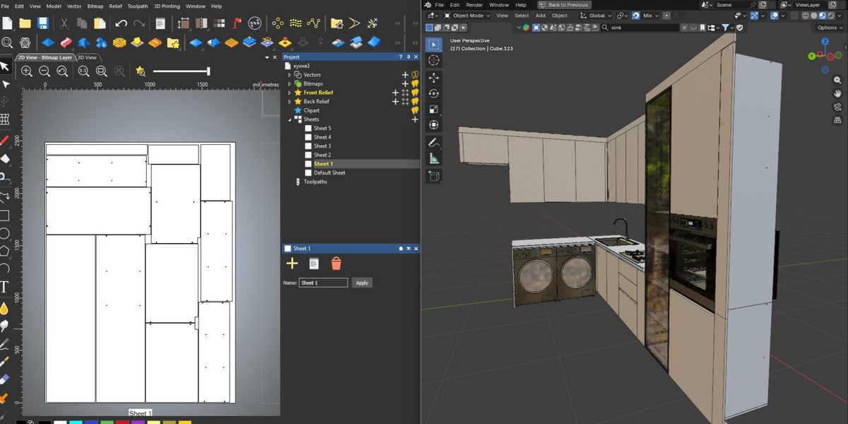




What ProCutter CNC Does
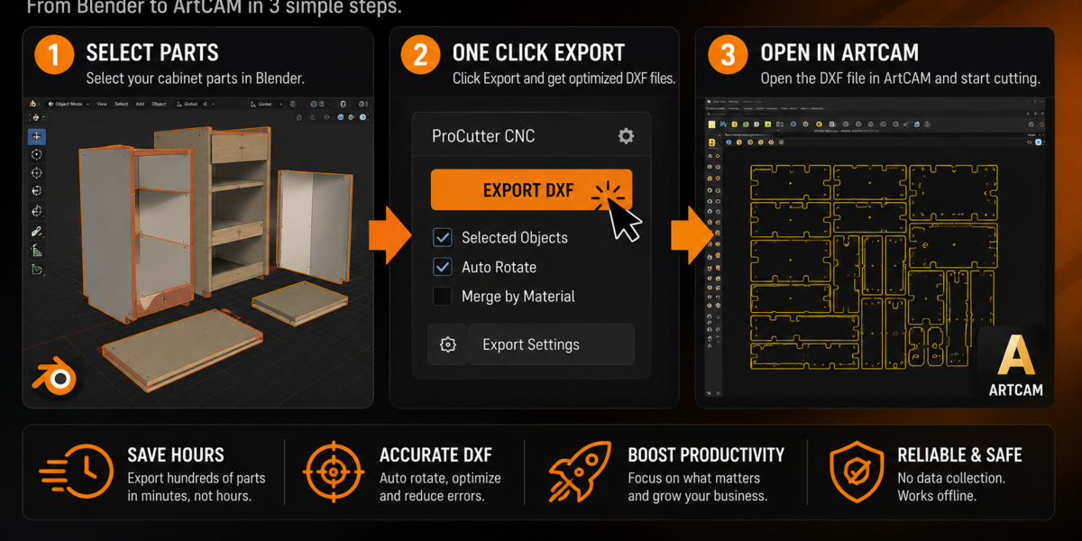
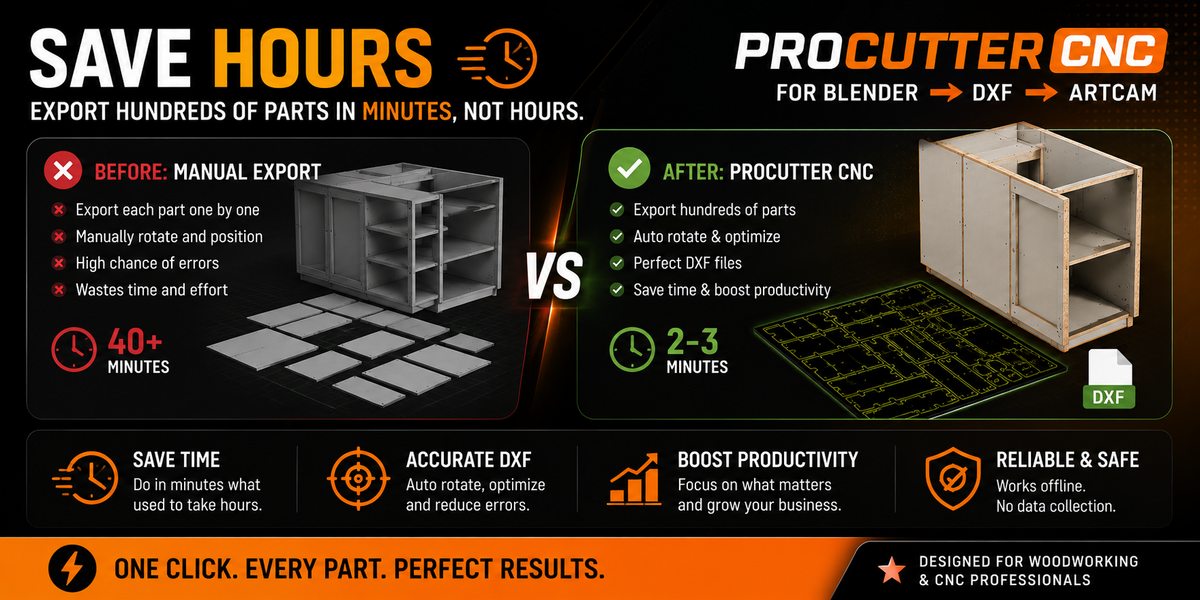
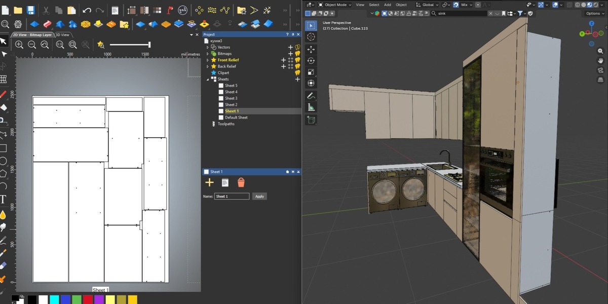
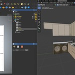
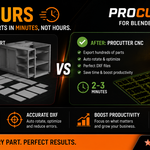
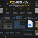
ProCutter CNC exports selected mesh objects from Blender as clean, production-ready DXF files for CNC routers, laser cutters, and plasma cutters. It automatically nests your parts onto a sheet, compensates for your tool's cutting width, sorts parts into separate files by material, and cleans up the resulting geometry — all from a single panel in the 3D Viewport sidebar.
Where to Find the Panel
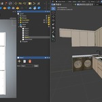
Open the 3D Viewport, press N to open the sidebar, and select the ProCutter CNC tab.
Basic Workflow
- Model or import your parts as flat meshes (Blender mesh objects).
- Select the object(s) you want to export. If an object has children (e.g. sub-parts parented to it), they are automatically included.
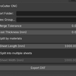
- In the ProCutter CNC panel, set:
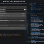
- Export Folder — where the DXF file(s) will be saved.
- Vertex Group (Optional) — restrict export to a specific vertex group instead of the whole mesh. Leave empty to export the full mesh.
- Merge Tolerance — distance (in the export's working units) within which duplicate points/edges are merged during cleanup.
- Tool Thickness (mm) — the diameter/width of your cutting tool. This value is added to the spacing between parts during nesting, so your bit or blade never cuts into a neighboring part.
- Split by materials — when enabled, parts are grouped by their assigned material and exported into separate DXF files (one per material). Objects without a material are grouped together into a file named "NoMaterial".
- Sheet Length / Sheet Width — the dimensions of your cutting sheet.
-
Split into multiple sheets — when enabled, parts that don't fit on one sheet are automatically placed on additional sheets, each saved as its own DXF file (e.g.
_sheet1,_sheet2).
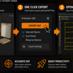
- Click Export DXF.
How Nesting Works
ProCutter CNC uses a Best-Fit Decreasing Height packing algorithm: larger parts are placed first, and each part is fit into the position that wastes the least horizontal space. This produces a tight, efficient layout without any manual dragging.
How Material Splitting Works
Each object's first assigned material is used as its "material group." When Split by materials is enabled, all parts sharing a material are packed and exported together into one DXF file, named yourfile_MaterialName.dxf. Objects without any material go into yourfile_NoMaterial.dxf. This is useful when a single scene contains parts meant for different sheet colors, thicknesses, or types of material.
How Tool Thickness (Kerf) Compensation Works
The value you set for Tool Thickness is added directly to the padding/spacing between parts during nesting. This means if your router bit is 3mm wide, parts will be spaced with an extra 3mm gap, preventing the tool path of one part from overlapping the next.
Output Files
- File names follow the pattern:
linear_export.dxf, or with material split:linear_export_MaterialName.dxf, or with multi-sheet:linear_export_MaterialName_sheet2.dxf. - Each part is placed on its own named DXF layer (named after the Blender object), making it easy to inspect or edit individual parts in your CAM software.
- Output DXF files are automatically cleaned: duplicate/overlapping lines within the Merge Tolerance are merged into single edges.
Compatibility
Exported DXF files (R2000 format) are compatible with common CAM/CAD software including ArtCAM, Aspire, VCarve, Fusion 360, SolidCAM, RhinoCAM, Mach3, LinuxCNC, EnRoute, and Type3, as well as general CAD tools like AutoCAD and Rhino.
Requirements
- Blender 5.1 or newer.
- Works with mesh objects; parts should be modeled as flat (2D-ish) shapes for best results, as the addon projects each part onto its best-fit plane (XY, XZ, or YZ) for export.
Have questions about this product?
Login to message
| Published | 3 months ago |
| Blender Version | 4.4 - 5.2 |
| Extension Type | N/A |
| Render Engine Used | Blender-Internal, Cycles, Eevee |
| License | Mit |

Discover more products like this
artcam furniture aspire addon CNC laser sheet layout dxf nesting wood linuxcnc fusuion360 procutter layout DXF export 2026 cutting solidcam woodworking manufacturing vcarve solid mdf cncmachine