Smart Cut & Bevel
 JuanBautista




Smart Cut & Bevel 1.3.8 RC2
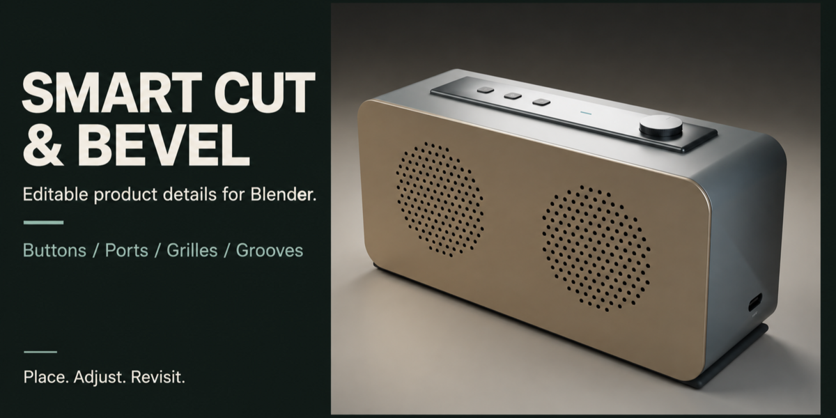
Editable microdetails for product and hard-surface design in Blender. Version 1.3.8 includes a cylinder-ring continuity correction. The supplied installer is 1.3.8 RC2.
Compatibility and installation
Blender 5.0 or later is the declared minimum. Fresh installation, upgrade and modeling regression checks passed on Windows with Blender 5.0.1 and 5.2.1 LTS. macOS and Linux addon operation are not verified. Rendering native geometry in Colab does not certify addon compatibility.
- Save your work and use a copy when testing.
- Open Edit > Preferences > Get Extensions > top-right menu > Install from Disk.
- Select
smartcut_bevel_v1.3.8_rc2.zipwithout extracting it. Enable the extension. - Restart Blender. In a 3D Viewport, press N and open Smart Cut. Shift+Q opens the pie menu.
- Select a mesh and choose Set Active as Target.
Updating from 1.3.7 beta1 or beta2: install the 1.3.8 RC2 ZIP and restart Blender. Do not enable an older legacy copy at the same time. Keep custom preset libraries outside the addon folder.
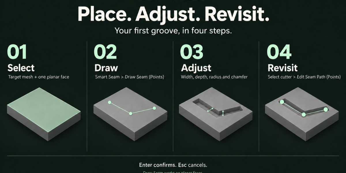
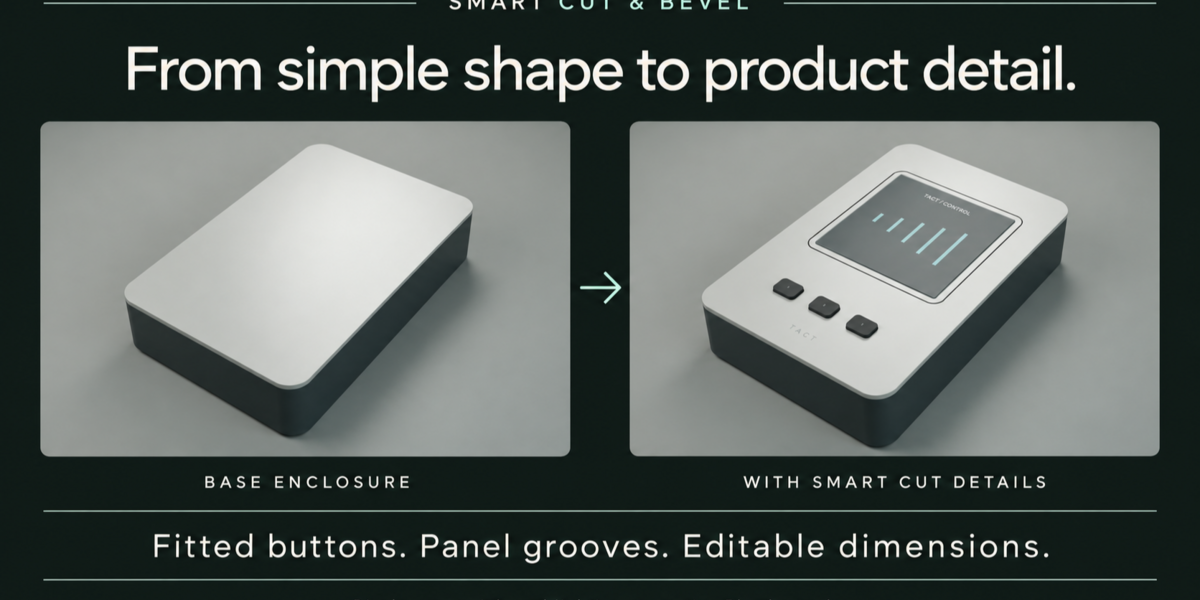
First exercise: draw a groove on a flat surface
- Select your target mesh and enter Edit Mode.
- Use face selection and select exactly one planar face.
- Expand Smart Seam. Draw Seam (Points) is the first action, above Predefined Shapes.
- Click two or more points. Enter creates the groove; Esc cancels.
- W adjusts width, D depth, R corner radius and B entrance chamfer. Type values with units when needed. C closes a path; do not repeat its first point.
- Select the resulting seam cutter and choose Edit Seam Path (Points) to revisit it.
- When a predefined contour is selected, use Select Target to Draw a New Path, then select a planar face in Edit Mode.
Point drawing remains planar. A cylinder ring is a dedicated circular groove; it does not make arbitrary drawn paths follow curved surfaces.
Target, cutters and safe editing
A Target is the mesh being modeled. A Cutter is a separate mesh linked to that target by an owned Boolean modifier. Start by selecting the mesh and using Set Active as Target. The active mesh or active cutter's Target takes precedence over the saved scene Target.
For face-based details, select the target, enter Edit Mode and select exactly one destination face. Planar Port, Vent and Seam tools require a planar reference. Surface Button, Layout and Grille have their own curved-surface support.
Use each tool's own editing controls to preserve its parameters and ownership. Manually editing generated meshes, adding unsupported mesh attributes, copying linked assemblies or moving their pieces independently can prevent further parametric edits. Follow diagnostics rather than deleting references to bypass them.
Smart Shell and Interior Insert
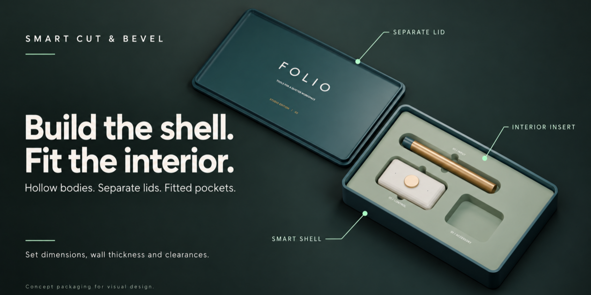
Smart Shell creates a rounded hollow body, separate lid and optional locating lip. Set overall dimensions, wall/floor/lid thickness and clearance before adding details. Move the assembly from its controller. Use Body/Lid selection and Hide Lid / Inspect Interior to inspect it.
Edit Assembly Dimensions can resize a supported original body/lid/insert together. It rejects dependencies and unsupported edits that would invalidate the assembly. Once the shell has cutters or attached details, save a base copy for proportion changes; Shell does not automatically reposition all those details.
Interior Insert creates fitted packing geometry with a regular pocket grid or captured object pockets. Configure insert clearances, pocket depth and Minimum Pocket Wall. Object captures are independent of their source after creation. Multi-pocket tools can add, replace and remove supported captures. Correct an invalid fit before rebuilding. These are modeling tools, not certified manufacturing tolerances.
Surface Button and Surface Layout
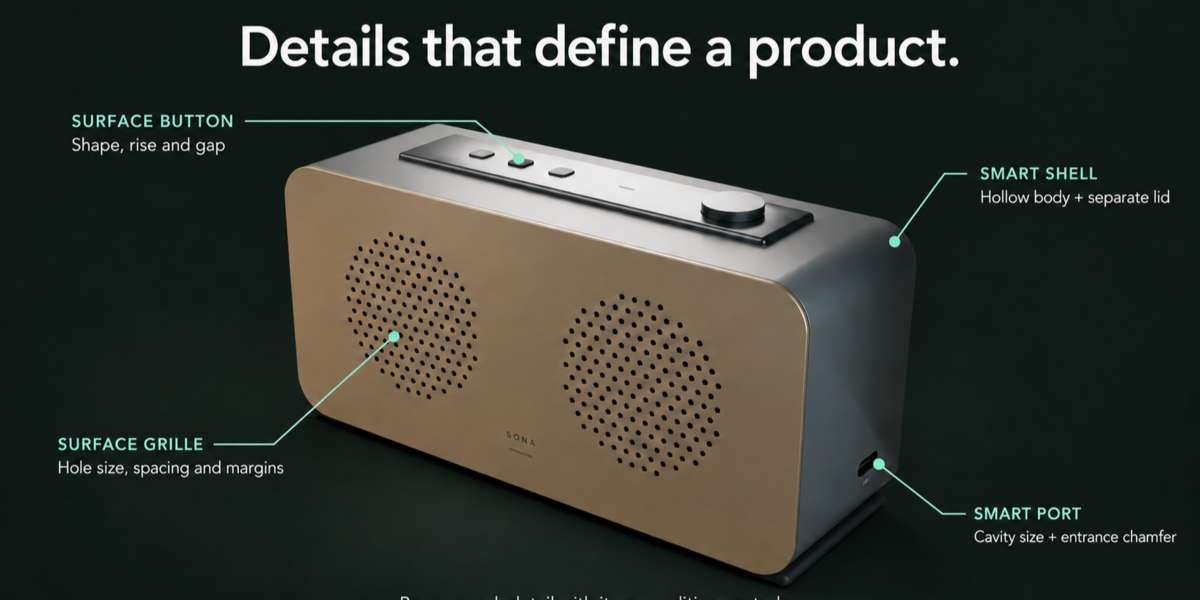
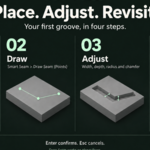
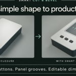
Select an exposed surface face and create a Surface Button. It builds a housing cutter and a separate cap. Shape controls the outline; Width/Height, Depth, Button Rise and Gap control the fit. Top Profile offers Flat, Domed and Concave; Profile Amount and Edge Rounding control the finish.
Use the original cap or housing to edit. Surface Layout distributes supported button details across a captured surface. Use the tool's controls instead of applying a generic rigid array to a curved assembly.
After changing the target surface, use Refit on Updated Surface and choose the new anchor on the target. Review the preview and confirm. Later details can need their own Refit; work in modifier/creation order. Refit does not continuously update while you deform the target.
Restore Surface Shading optionally samples smooth exterior normals from the captured reference. Keep its Geometry Nodes modifier immediately after its associated Boolean. Remove Surface Shading removes only this owned finish. It preserves geometry and cut dimensions; it does not repair insufficient mesh resolution or complex custom-normal boundaries.
Surface Grille
Select one exposed outer face on a hollow shell and choose Surface Grille (Beta) > Create Grille. The dialog previews bore outlines before creating objects.
- Area Radius: circular pattern area in the anchor projection.
- Hole Diameter: size of the circular bores.
- Minimum Web: conservative separation between finite bores, including their convergence inside the wall.
- Outer Margin / Clear Center Radius: preserve material at the boundary or reserve a central control area.
- Pattern Rotation: orientation of the staggered grid.
- Max Wall: explicit maximum local wall thickness to cross.
- Through Local Wall: measure and cross the first wall, stopping before another wall.
- Manual Depth: specified depth must clear the local wall without reaching the next one.
- Hole Segments: contour resolution.
Select the original grille cutter to use Edit Grille. Grid pitch can expand to preserve Minimum Web; hole count can change. There is one compound cutter, one Boolean and one captured reference. Delete Grille removes this assembly when no external dependencies prevent safe removal.
After deforming the shell or changing thickness, select the cutter and choose Refit Grille on Updated Surface. Review the outlines and parameters, then confirm. Escape preserves the old assembly; Undo restores the previous result. Objects, materials and the owned Surface Shading modifier are retained.
Grille Refit finds an exposed surface along the previous anchor axis. Movement beyond the original area radius is rejected; create another grille for a different location. Refit does not promise to retain hole count. Update downstream details such as a central button afterward.
Scope: up to 256 circular holes on a convex patch, within 55 degrees of the anchor axis, on a connected closed evaluated boundary. An open-backed dome with a closed Solidify rim is supported. Disconnected inner/outer boundaries of a sealed hollow sphere, full 360-degree wrapping, freeform borders, grille library recipes and geodesically uniform spacing are unsupported. Footprint sampling is a modeling check, not acoustic or fabrication validation.
Smart Port and Smart Vent
Select one planar target face. Create a centered detail or use interactive placement. Port provides rounded rectangular cavities and an optional entrance chamfer; Vent provides slot layouts.
During viewport adjustment use W/H/D for dimensions and R for rotation. Port additionally uses C for corner radius and B for entrance chamfer. Drag to adjust; Shift gives precision. Type a value with optional units, for example 2mm. Enter accepts that value, and another Enter confirms the operation. Escape first cancels an active parameter adjustment and then the session. Watch the HUD for the current stage.
Select the original cutter to reopen its parameter or viewport controls. Do not use native object scale to resize a parametric Port or Vent. Leave room for chamfers and neighboring cuts; these tools do not automatically clip to a face or prevent all collisions.
Smart Seam
Select one planar target face and choose Draw Seam (Points). Click to add points; C toggles a closed path and E switches the supported end style. Do not repeat the first point to close the loop. W changes width, D depth, R corner radius and B entrance chamfer. Enter commits a valid path.
Edit Seam Path (Points) reopens handles. Select a point and use G to move it; Ctrl+Click inserts a point on a segment; Backspace/Delete removes the selected point. Dimensions & Finish provides numeric settings. Up to 64 control points are supported; crossings, collapsed offsets and corners that do not fit are rejected. Seams remain planar and create grooves rather than separate panels.
Seam contours and Cylinder Ring
Select one planar exterior face in Edit Mode, then Smart Seam > Create Seam Contour: Rectangle, Square, Circle or Ellipse. Set dimensions, groove width/depth, corner radius, entrance chamfer, Anchor U/V and rotation. The preview checks the evaluated surface and rejects cuts outside the patch or through the wall.
For Cylinder Ring, select a straight circular cylinder and choose its local X/Y/Z axis. Ring Height from Center positions the groove along that axis. Use at least 32 sides (64 recommended). Rings reject rims, existing cuts within the band, noncircular sections and depths that pierce a hollow wall. Select the original cutter to Edit Contour / Ring or Delete Seam Contour. Use its parameters to reposition it.
These are shallow grooves, not physical shell separation. Draw Seam remains planar; arbitrary curved paths and spheres are unsupported.
Guided values and placement
New contour and grille dialogs suggest dimensions from the selected patch and its first wall, and show the measured thickness. Existing saved details keep their own settings. Invalid depth/wall messages include values in scene units; suggestions do not bypass validation.
Use Place Contour in Viewport / Place Ring in Viewport to create, or select a contour cutter and use Move in Viewport to reposition. Hold the left mouse button and drag. Enter confirms; Esc cancels without modifying the scene. MMB/wheel navigate. For rings, drag over the visible cylinder wall. Height Input supports Distance from Center or Percentage of Height (50% = center).
Preset libraries and patterns
The Parametric Library stores supported Port, Vent, Button/Layout and Seam recipes as JSON, not arbitrary materials, modifiers, object transforms or manual mesh edits. Select the detail to save; select an appropriate destination face to load. Preserve Physical Size converts length parameters between scene unit scales when supported. Scene units set to None retain local Blender values.
Seam Preview Placement supports G move, R rotate and S scale the path. X/Y constrain movement; P changes the pivot. Hold Ctrl during movement/rotation to snap to supported references from the captured face. Confirm a transform, then confirm placement. Escape first restores the transform, then cancels placement. Width/depth/corner/chamfer remain unchanged when scaling the path.
Patterns supports Linear, Grid and Radial repetition for compatible cutters. It is not a replacement for curved Surface Layout or Surface Grille. Radial patterns use the target origin and local Z axis. Unsupported combinations are guarded.
Materials & Mesh Presets is a separate library for mesh-based cutters and materials. Store user libraries in a writable location outside the addon installation.
Smart Draw, stack and finishing
Smart Draw creates Difference, Union, Intersect and Slice cuts. Hover the target for surface feedback. Ctrl temporarily enables increment snapping; Shift constrains a box to a square; Alt draws from center. Type a planar size such as 2x1, then an extrusion depth. D/U/I/S chooses the operation while drawing.
Edit Transform & Operation provides S local size, G movement, R rotation, and X/Y/Z or Tab axis selection for compatible cutters. O cycles the supported Boolean operations. Escape restores the session. Specialized assemblies use their own editors.
SmartCut Stack selects and manages owned Boolean relationships. Follow warnings before duplicating, reordering or unlinking details. Bevel/Weld/normal finishing follows the owned cut block. Freeze Smart Cut Stack ends the applicable editable workflow; keep a separate project copy before committing a final mesh. Protected assemblies must use their own supported actions.
Troubleshooting
- Panel missing: confirm the extension is enabled, use a 3D Viewport and press N. Restart after upgrading.
- Target changed: use the appropriate Refit where supported; planar tools may need recreation on a new reference.
- Grille fails: begin with a small area, check a closed connected wall, the selected outer face, Max Wall and clearance. Increasing depth indiscriminately can reach the opposite wall.
- Cannot edit a generated part: restore unsupported manual transforms/mesh edits or recreate the detail through its own tool. Native duplicates are not independent assemblies.
- A later detail requests Refit: its reference predates an upstream change. Update details in creation/modifier order.
- Unexpected shading: inspect source smoothing, the Boolean result, modifier order and Surface Shading. The tool cannot replace adequate source geometry.
License
GPL-3.0-or-later; see LICENSE. The ZIP includes the addon source. See CHANGELOG.md for historical changes.
Support and updates
Includes 12 months of support and updates from purchase. Support through the Superhive inbox covers installation and reproducible issues in documented workflows. Responses within three business days, excluding weekends and holidays. We make a good-faith effort to maintain compatibility with the current Blender LTS. Versions received during the support period remain yours permanently. Renewal for another 12 months is optional, at 50% of the current product price. No automatic renewal.
For an issue report, include Blender and OS versions, reproduction steps, the console error and a minimal .blend file when available. Custom modeling commissions and manufacturing validation are not included.
 Included
Includes 12 months of
- Support from JuanBautista
- Product updates
Extend this product’s Support Period +12 months: 50% of product price
Have questions before purchasing?
Login to message
| Blender Extension Compatible | Yes |
| Published | 3 days ago |
| Blender Version | 5.0 - 5.2 |
| Extension Type | Add-on |
| License | GPL |
Discover more products like this
modeling product Design bevel hard surface microdetails shell perforations boolean seams buttons