Tykuii's Level Design Toolkit
 tykuii's lil shop


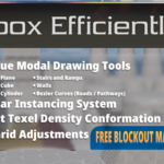
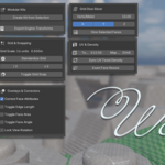
Tykuii’s Level Design Toolkit Overview

Material Slot
A dropdown that allows you to select a material that exists within the current Blend File. This material will be applied to all relevant operations (excluding Bezier Roads).
1x1 Block
Creates a 1 by 1 meter block at the origin of the world, with a corner based origin point.
1x1 Plane
Creates a 1 by 1 meter plane at the origin point of the world, with a corner based origin point.

Corner
Set the origin point to a corner and zero the transforms (set to world origin). Repeated clicks will toggle which corner the origin is placed at. Uses the furthest vertex on each respective angular direction.
Center
Sets the origin point to the center of the Object and zeros the transforms (sets to world origin).
Btm Center
Sets the origin point to match the lowest vertex, with a weighted placement on x-y.
- X Edge
Sets the origin point to match the furthest negative vertex on the X and Z axis, with a weighted placement for Y.
+ X Edge
Sets the origin point to match the furthest vertex on the X and Z axis, with a weighted placement for Y.
- Y Edge
Sets the origin point to match the furthest negative vertex on the Y and Z axis, with a weighted placement for X.
+ Y Edge
Sets the origin point to match the furthest vertex on the Y and Z axis, with a weighted placement for X.
Quick Mirror
Mirror’s the object based on its current origin point and a temporarily created “dummy plane”.
Move the mouse left and right during the operation to rotate the dummy plane.
Hold Ctrl to snap the angle during the operation.
Left click or press enter to confirm the operation.
Right click or press escape to cancel the operation.


Plane
Draws out a plane based on the viewport and current grid size. Click on the operation, then click-drag in the scene to specify the plane size.
Enter or left mouse click to confirm the operation. Right click or escape to exit the operation.
Box
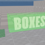
Draws out a box based on the viewport and current grid size. Click on the operation, then click drag in the scene to specify the plane size. Afterwards, move your mouse up or down to specify height.
Left click or enter to confirm the operation. Right click or escape to exit the operation.
Stairs / Ramp
Draws out stairs or a ramp based on the viewport and current grid size. Click on the operation, then click-drag in the scene to specify the plane size. Afterwards, move your mouse up to specify stair height. Downward stairs currently do not properly function. Scroll to specify step count. Press R to rotate the direction of the incline. Press T to switch between stairs and ramps.
Enter or left mouse click to confirm the operation. Right click or escape to exit the operation.
NEW: Now works on walls. Will project downward.
Cylinder
Draws out a cylinder based on the viewport and current grid size. Click on the operation, then click-drag in the scene to specify the radius. Afterwards move the mouse up or down to specify height.
Enter or left mouse click to confirm the operation. Right click or escape to exit the operation.
Straight Wall
Draws out a wall based on the viewport and current grid size. Click on the operation, then click a point in the scene to specify the end of the wall. Afterwards, scroll up or down to specify height.
Enter or left mouse click to confirm the operation. Right click or escape to exit the operation. The operation will confirm whatever is visually present, not just the last click.
Curved Wall
Draws out a curved wall based on the viewport and current grid size. Click on the operation, then click a point in the scene to specify a handle position. Keep clicking to add more points. Afterwards, scroll up or down to specify height.
Enter or left mouse click to confirm the operation. Right click or escape to exit the operation. The operation will confirm whatever is visually present, not just the last click.
A solidify modifier is created associated with the curved wall. Go to the modifiers section in your properties panel to adjust the size as needed.
Surface Path
Draws out a road / Bezier Curve based on the viewport and current grid size. Click on the operation, then click a point in the scene to specify the starting position. Click and click-drag allows the user to add new points and seamlessly adjust the handles per point in order of clicks. Afterwards, scroll up or down to specify height.
Enter or left mouse click to confirm the operation. Right click to undo the last step. Escape to exit the operation. The operation will only confirm up to the last click, not what is visually present.
Custom Profile
Select the profile of the Arch to be used during the Draw Modal Arch operation.
Select between the following:
Arc
Perfect Circle (Semi-Circle)
Gothic
Lancet (Sharp Gothic)
Tudor (Depressed)
Ogee
Bell Curve
Triangle
Square
Shouldered
Corbel
Parabola
Catenary
Custom Profile
Segments
Pre-emptively specify the segment count before entering the Draw Modal Arch operation.
Height
Pre-emptively specify the height of the arch before entering the Draw Modal Arch operation.
Blender’s Custom Profile
Typical ui window found within blender for custom profiles for beveling and such. The controls are 1:1 with what blender offers.
The profile is what will be utilized if Custom Profile is selected as the mode during the Draw Modal Arch operation.
Draw Modal Arch (Edge)
Select a singular edge during the blockout phase.
Run the operation
Move mouse left and right to adjust the height of the arch.
Press C to change the shape profile.
Scroll the mouse wheel to adjust the quantity of segments (arch resolution).
Left mouse button or press the enter key to confirm the operation.
Right mouse button or press the escape key to exit the operation.

Clean Triangulate
Finds all the N-Gons on an object, and perform’s blenders ‘beauty’ triangulation on those specific faces.
Grid Dice Slicer: Verts / Meter
Specify the vertex density desired on the selected faces.
Grid Dice Slicer: Cutting Plane
Select the plane to project the grid from (X-Y, X-Z, Y-Z)
Grid Dice Slicer: Dice Selected Faces
Performs the dicing operation based on the above parameters.


Create Kit from Selection
Collapsed Modular Kit Section
Click to expand the section.
Expanded Modular Kit Section
Prepare Master for Export
Simple Master Origin Manipulation that retains the positions of all instances.
Modular Kit Instance Randomization (Experimental)
Locational Jitter (m): Randomize the location based on the permitted axes (x,y,z).
Z-Rotation Snap with Random Z Rotation Checked:
Rotate about Z-axis randomly
Scale Variance +/-: Specify scale tolerance deviation from source.
Isolate Master Object
Frames the camera to the source master object. Isolates the view.
Removes tracking of the Modular Kit Collection, no longer visible in panel.
Modular Kit Instanced Object
Edit Instance
Frames camera to the listed instanced object. Enters edit mode.
Rotate Instance about Z-Axis.
Rotate Instance about Y-Axis.
Rotate Instance about X-Axis.
Mirror Instance across specified Axis in the popup window.
Removes specified instance from the list and unlinks it, so it is no longer an instanced object.
Creates a new Modular Kit collection from the selection, keeping the list item’s transform locations and creating a new source object at the origin point. Great for quick variant work.
Change the point utilized in the fitting algorithm to better match the positioning between a new instanced object and the source object, based on the source object’s current directionality.
Add the currently selected object or face to the Modular Kit collection as a new instance, replacing the geometry with the source.
Currently will try to calculate best position for the replacement, but it is not a guarantee it will fit 100% of the time.
Replace the Modular Kit’s master/source object with the active selected object.
Export text transform values based on the target engine.
Click on the operator.
Select the target engine and desired origin point.
Open the text editor.
Browse text to be linked.
Modular_Export_(TargetEngine) will exist and update.
Great for recreating instantiated objects in-engine using transform values.

Standardize Grid
Allows the user to pick a grid befitting a specified game engine or to use a custom grid scale.
Divide the grid by 2 at its current scale.
Multiply the grid by 2 at its current scale.
Toggle between the previous snapping options and snapping options required for grid based workflows.
Texels/m
Set the Texel Density (TD) of the scene. To be utilized in the “Sync UV Texel Density” operation.
Map Size
Set the expected texture map size, in pixels.
Sync UV Texel Density
Scales the UVs to conform to the specified Texels / m using the specified texture size. If no seams are detected, it will perform a cube projection unwrap on the geometry before the reallocation and resizing operations.
UVs will be laid out in a manner that resembles world orientated UVs. The user is expected to do any final tweaks required of the scene before export.
Exact Face Resize
Specify a corner or edge of a face to lock in place. Slides the rest of the face and border geometry in order to meet the required face size.
Correct Face Attributes
Native blender toggle that allows for UVs to be manipulated during modal edit mode operations to ensure no stretching or deformations.
Toggle Edge Length
Native blender edit mode overlay that displays edge length in the scene’s units.
Toggle Face Area
Native blender edit mode overlay that displays selected face area in the scene’s units.
Toggle Face Angle
Native blender edit mode overlay that displays face angles on selected geometry.
Lock View Rotation
Locks the viewport camera to prevent accidental rotation during particular operations.
NEW: Create an area grid from drawn lines.
NEW: Create an area grid from drawn curves.
Texture Map Materials (Quickest Installation)
Drag and drop the textures into the shader graph.
Connect colored images or images with _c into the Base Color or directly into the surface ports.
_r and _e stand for roughness and emission respectively. Drag their sockets into the roughness and emissive ports if available respectively.
Terrain Toolkit:

Initialize Terrain: Sets up the blender scene to track terrain chunks. Required to start using Terrain Tools.
Settings:
Target Engine: Define the target engine (Blender is a safe default; Only changes conventions used in the processes).
Grid Scale: Define the size of each terrain chunk.
Resolution: Define the amount of vertices per terrain chunk.
Material: Define the blender material (existing in the scene) to use when creating new terrain chunks.
Base Vertex Color: Define the starting vertex colors per new terrain chunk.
Selected Chunk: Visible when a terrain chunk is selected.
Add Heightmap Displacement: Adds a displacement modifier to the selected chunk directly in the panel with matching parameters.
Conform Borders: Experimental feature to attempt to force-match border vertices. Currently it does not function well with corners.
Sync Geometry Heights: Experimental feature to blend chunks.
Gradient Blending: Blends the selected chunk to neighbors with a gradient influence to help match heights better. Currently has issues with corner vertices.
Linear Blending: Blends the selected chunk to linear neighbors only. Currently more stable.
Seam Shading: Tools to attempt to help blend normals between nonmatching geometry.
Bake Seamless Shading: The process is similar creating a duplicate -> joining and merging the chunks -> transferring the normal data to the original chunks individually and applying.
Averages normals between neighbors to attempt better normals.
Paint Normal Mask: The processes above can detract from desired normal details. Painting areas where you want normal blending operations to occur through this operation saves normals elsewhere.
Rotate CCW and Rotate CW:
Rotate the selected chunk counterclockwise or clockwise.
Swap: Having two chunks selected, properly swap places between the chunks while retaining proper tracking in the terrain grid system.
Delete: Delete and properly remove the selected chunk from the terrain grid system.
Merging:
Merge the selected chunks and enter sculpt mode for sculpting operations.
Lock X/Y Sculpting: Toggles a lock so that users can only sculpt on Z axis if desired.
Separate Into Original Chunks: Properly separate the merged chunks and retain terrain grid system tracking. Good for sculpting detail between borders.
Export:
Export Coordinates to Text: Stores the names and their coordinates of each terrain chunk to a text block to recreate in desired game engine.
Prep Meshes for Export: Zeros the transforms of all terrain chunks returning them to world origin.
Emergency Reset: If issues arise with the terrain chunk system, pressing this button will reset the system and allow for reinitialization.
Best example: Deleting a terrain chunk piece manually without having a second available to add more! Silly quirk of data tracking that I haven’t accounted for yet.
Have questions about this product?
Login to message
| Blender Extension Compatible | Yes |
| Sales | 10 |
| Published | 5 months ago |
| Blender Version | 5.1 - 5.2 |
| Extension Type | Add-on |
| Render Engine Used | Blender-Internal, Cycles, Eevee |
| License | GPL |