 Dmitrii Smirnov


| Physics-driven material optimization for FDM
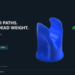
Stop printing the plastic your structure does not need.GaudiTopo turns a closed design volume into a lighter, load-aware structure. You keep the material that carries the load and remove the volume that only consumes filament. MEASURED EXAMPLES: 30.8–45.1% LESS MATERIAL
|
A printable part should contain the material it needs, not every cubic millimetre you happened to model.
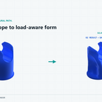
Traditional modelling makes a solid envelope first and asks engineering questions later. GaudiTopo reverses that logic: define the supports, loads and material, then let structural usefulness decide where the plastic remains.
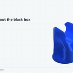
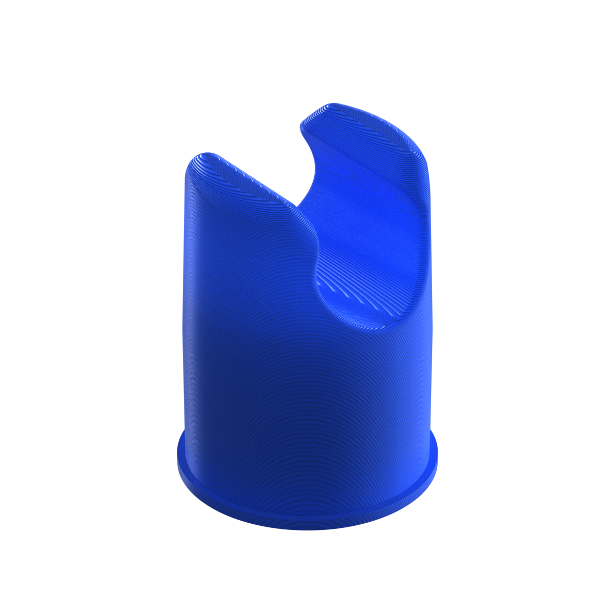
| 01 / Solid design volume
 |
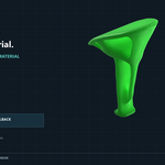
→ | 02 / Result + saved volume
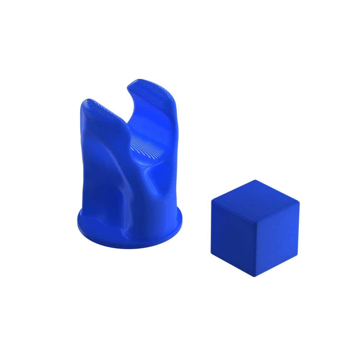 |
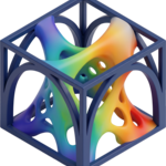
The cube is not decoration. Its volume equals the material removed from the displayed mesh. At 1.75 mm filament diameter, this example represents approximately 4.95 metres of filament.
The benefit is visible, measurable and printable.
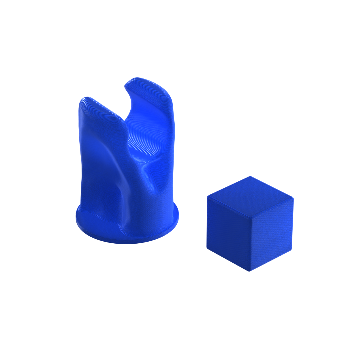 32.4%
material saved11.9 cm³ · 4.95 m filament 1.48× parts per equal volume |
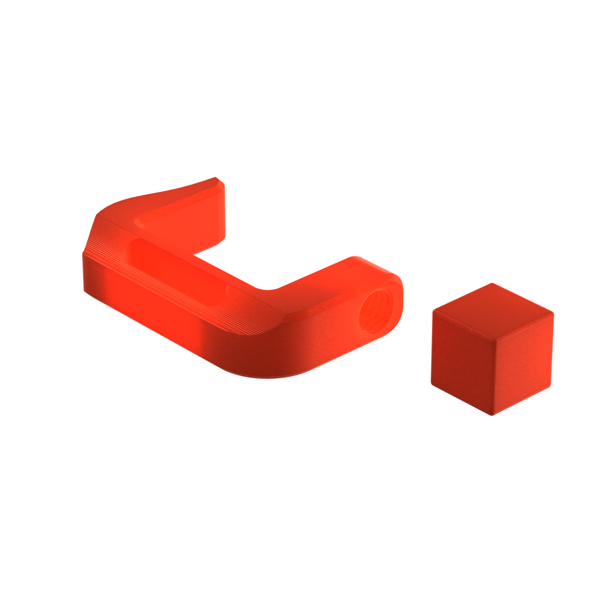 30.8%
material saved9.8 cm³ · 4.08 m filament 1.45× parts per equal volume |
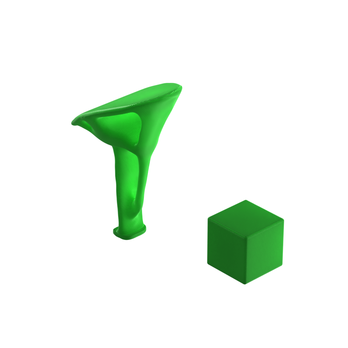 45.1%
material saved19.1 cm³ · 7.94 m filament 1.82× parts per equal volume |
Volumes were measured from the displayed evaluated meshes. Filament equivalents use 1.75 mm diameter. Results vary by geometry, material, boundary conditions, loads and engineering settings.
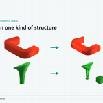
| A / A design shaped by its job
Structures that would be painful to model by hand.The result is not a random organic shell. Branches, openings and ribs emerge from the relationship between supports and loads. Change the engineering study and the structural language changes with it, giving each functional part its own recognisable form. |
B / Less polymer per useful part
Better material efficiency is better project economics.Using less feedstock for the same defined engineering purpose means more parts from the same material supply and less unnecessary polymer locked into every print. It is a practical ecological improvement: reduce material at the design stage instead of treating waste after it already exists. |
GaudiTopo removes material through real 3D finite-element calculations.
The addon discretises the design domain, solves equilibrium under the supplied loads and supports, evaluates how useful each material region is, updates the density field and repeats. The output is then reconstructed as geometry and can be independently re-voxelised and checked again.
|
K(ρ)u = F
FEM equilibrium under the defined boundary conditions.
|
C = Fᵀu
Compliance measures structural flexibility and guides stiffness.
|
E(ρ)=Emin+ρᵖ(E₀−Emin)
SIMP links element density to effective stiffness.
|
SF = σallow / σvm,max
Safety-factor evidence is evaluated against the material profile.
|
In plain words: loads create displacement and stress; the optimizer keeps density where it improves the structural response and removes it where it contributes less.
You define the engineering problem. GaudiTopo explores the material.
| 01 |
Uniform Mesh Create and visually approve a predictable engineering mesh. |
| 02 |
Material, Supports and Loads Choose an FDM profile, freeze support faces and define up to 10 loads across multiple cases. |
| 03 |
Pre-analysis Catch ambiguous or unusable boundary conditions before the full study. |
| 04 |
Target SF Search + SIMP Repeated FEM solves search for a lighter structure around the selected engineering target. |
| 05 |
Independent Verification Rebuild the delivered surface as a separate analysis problem and report final evidence. |
Built for practical FDM exploration
| ✓ Work directly inside Blender | ✓ Six FDM material profiles |
| ✓ Force, pressure, bearing, moment and remote force | ✓ Up to 10 loads and multiple load cases |
| ✓ Live density and stress-utilisation preview | ✓ PASS, REVIEW and FAILED engineering feedback |
| ✓ Native C++ with optional CUDA acceleration | ✓ Included CPU fallback route |
Requirements
|
Honest engineering note
Numerical evidence is not physical certification.GaudiTopo is an engineering exploration and screening tool. Its results are physically based within the supplied geometry, material assumptions, boundary conditions and numerical settings. Calibrate profiles for the real printer, filament, orientation, infill and manufacturing defects, then physically test every real load-bearing part. |